Product Description
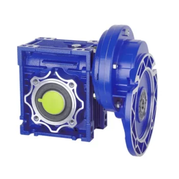
High Rpm RV series Aluminum Alloy Worm Gear box NMRV 571-150 Reducer Variable Wheel Drive Speed Reduction Worm Gearbox
Product Parameters
Editing and broadcasting of main materials
1. Body, die-casting aluminum alloy;
2. Worm shaft, 20 Crq steel, high temperature treatment;
3. Worm gear, nickel bronze alloy;
4. Aluminum alloy body, sandblasting and surface anti-corrosion treatment;
5. Cast iron body, painted with bIu RA5571.
Regular center distance specification editing and broadcasting
Center distance: 130 (unit: mm).
Output hole/shaft diameter: 11, 14, 18, 25, 28, 35, 42, 45 (unit: mm)
Products Description
NMRV worm gearbox reducer is a commodity with sophisticated design and continuous improvements, its main features are made of high quality aluminum alloy, light weight and non-rusting, larget output toque, smooth running and low noise, high radiating efficiency, good looking apprearance, derable service life, small volume and suitable for all mounting positions.
Feature
1. Mad of high-quality aluminum alloy,light weight and non-rusting
2. Large output torque
3. Smooth in running and low in noise,can work long time in dreadful conditions.
4. High in radiating efficiency.
5. Good-looking in appearance,durable in service life and small in volume.
6. Suitable for omnibearing installation.
contact-info.html
|
Model |
NMRV571, NMRV030, NMRV040, NMRV050, NMRV063, NMRV075, NMRV090, NMRV110, NMRV130, NMRV150 |
|
Ratio |
5,7.5,10,15,20,25,30,40,50,60,80,100 |
|
Output Torque |
1.8-1760Nm |
|
Application |
Machinery Industry |
|
Input Speed |
900-2800RPM |
|
Output Speed |
10-250RPM |
|
Material |
Housing: Size 25-110 Is Aluminum Alloy, Size 110-150 Is Cast-Iron |
|
Worm Wheel: ZCuSn10Pb1 |
|
|
Worm:20Cr |
|
|
Pinion:Tin Bronze |
|
|
Output Shaft: Steel-45# |
|
|
IEC Flange |
IEC Standard Flange Or On Customer Request |
Detailed Photos
Exploded View:
About CHINAMFG Transmission:
We are a professional reducer manufacturer located in HangZhou, ZheJiang province.
Our leading products is full range of RV571-150 worm reducers , also supplied GKM hypoid helical gearbox, GRC inline helical gearbox, PC units, UDL Variators and AC Motors, G3 helical gear motor.
Products are widely used for applications such as: foodstuffs, ceramics, packing, chemicals, pharmacy, plastics, paper-making, construction machinery, metallurgic mine, environmental protection engineering, and all kinds of automatic lines, and assembly lines.
With fast delivery, superior after-sales service, advanced producing facility, our products sell well both at home and abroad. We have exported our reducers to Southeast Asia, Eastern Europe and Middle East and so on.Our aim is to develop and innovate on basis of high quality, and create a good reputation for reducers.
| Hardness: | Hardened Tooth Surface |
|---|---|
| Installation: | 90 Degree |
| Layout: | Expansion |
| Gear Shape: | Bevel Gear |
| Step: | Single-Step |
| Type: | Gear Reducer |
| Samples: |
US$ 30/Piece
1 Piece(Min.Order) | |
|---|
Maintenance Tips for Prolonging the Life of a Worm Gearbox
Proper maintenance is essential to ensure the longevity and reliable performance of a worm gearbox. Here are some maintenance tips to consider:
- Lubrication: Regularly check and replenish the lubricant in the gearbox. Use the recommended lubricant type and quantity specified by the manufacturer.
- Lubrication Schedule: Follow a lubrication schedule based on the operating conditions and manufacturer recommendations. Regular lubrication prevents friction, reduces wear, and dissipates heat.
- Temperature Monitoring: Keep an eye on the operating temperature of the gearbox. Excessive heat can degrade the lubricant and damage components.
- Cleanliness: Keep the gearbox and surrounding area clean from debris and contaminants. Regularly inspect and clean the gearbox exterior.
- Seal Inspection: Check for any leaks or damage to seals and gaskets. Replace them promptly to prevent lubricant leaks and contamination.
- Alignment: Ensure proper alignment between the worm and worm wheel. Misalignment can lead to increased wear and reduced efficiency.
- Torque Monitoring: Monitor the torque levels during operation. Excessive torque can cause overloading and premature wear.
- Regular Inspections: Periodically inspect all components for signs of wear, damage, or unusual noise. Replace worn or damaged parts promptly.
- Proper Usage: Operate the gearbox within its specified limits, including load, speed, and temperature. Avoid overloading or sudden changes in operating conditions.
- Expert Maintenance: If major maintenance or repairs are needed, consult the manufacturer’s guidelines or seek the assistance of qualified technicians.
By following these maintenance tips and adhering to the manufacturer’s recommendations, you can extend the lifespan of your worm gearbox and ensure its optimal performance over time.

How to Calculate the Input and Output Speeds of a Worm Gearbox?
Calculating the input and output speeds of a worm gearbox involves understanding the gear ratio and the principles of gear reduction. Here’s how you can calculate these speeds:
- Input Speed: The input speed (N1) is the speed of the driving gear, which is the worm gear in this case. It is usually provided by the manufacturer or can be measured directly.
- Output Speed: The output speed (N2) is the speed of the driven gear, which is the worm wheel. To calculate the output speed, use the formula:
N2 = N1 / (Z1 * i)
Where:
N2 = Output speed (rpm)
N1 = Input speed (rpm)
Z1 = Number of teeth on the worm gear
i = Gear ratio (ratio of the number of teeth on the worm gear to the number of threads on the worm)
It’s important to note that worm gearboxes are designed for gear reduction, which means that the output speed is lower than the input speed. Additionally, the efficiency of the gearbox, friction, and other factors can affect the actual output speed. Calculating the input and output speeds is crucial for understanding the performance and capabilities of the worm gearbox in a specific application.

How Does a Worm Gearbox Compare to Other Types of Gearboxes?
Worm gearboxes offer unique advantages and characteristics that set them apart from other types of gearboxes. Here’s a comparison between worm gearboxes and some other common types:
- Helical Gearbox: Worm gearboxes have higher torque multiplication, making them suitable for heavy-load applications, while helical gearboxes are more efficient and offer smoother operation.
- Bevel Gearbox: Worm gearboxes are compact and can transmit motion at right angles, similar to bevel gearboxes, but worm gearboxes have self-locking capabilities.
- Planetary Gearbox: Worm gearboxes provide high torque output and are cost-effective for applications with high reduction ratios, whereas planetary gearboxes offer higher efficiency and can handle higher input speeds.
- Spur Gearbox: Worm gearboxes have better shock load resistance due to their sliding motion, while spur gearboxes are more efficient and suitable for lower torque applications.
- Cycloidal Gearbox: Cycloidal gearboxes have high shock load capacity and compact design, but worm gearboxes are more cost-effective and can handle higher reduction ratios.
While worm gearboxes have advantages such as high torque output, compact design, and self-locking capability, the choice between gearbox types depends on the specific requirements of the application, including torque, efficiency, speed, and space limitations.


editor by CX 2023-10-11
China high quality Gear Drive Gearbox for Electric Motor Gear Box Speed Drive China Manufacturer High Quality Good Price Reduction Electric Transmission Part Alloy Stainless Steel supplier
Product Description
Gear Drive Gearbox for Electric Motor Gear Box Speed Drive China Manufacturer High Quality Good Price Reduction Electric Transmission Part Alloy Stainless Steel
Application of Gear Drive Gearbox
Gear drives are used in a wide variety of applications where it is necessary to transmit power from 1 shaft to another. They are characterized by their ability to transmit power efficiently and smoothly, and they can be used to increase or decrease the speed of the output shaft. Some of the most common applications for gear drives include:
- Machine tools: Gear drives are used in machine tools to transmit power from the motor to the cutting tool. This allows the cutting tool to move in a variety of directions, including up and down, left and right, and CHINAMFG and backward.
- Robotics: Gear drives are used in robotics to transmit power from the motor to the robot arm. This allows the robot arm to move in a variety of directions, including up and down, left and right, and CHINAMFG and backward.
- Wind turbines: Gear drives are used in wind turbines to transmit power from the rotor to the generator. This allows the generator to generate electricity.
- Conveyor belts: Gear drives are used in conveyor belts to transmit power from the motor to the conveyor belt. This allows the conveyor belt to move materials from 1 place to another.
- Lifts and elevators: Gear drives are used in lifts and elevators to transmit power from the motor to the hoisting mechanism. This allows the hoisting mechanism to raise and lower the lift or elevator.
- Automotive: Gear drives are used in automotive applications to transmit power from the engine to the wheels. This allows the vehicle to move CHINAMFG and backward.
- Aircraft: Gear drives are used in aircraft applications to transmit power from the engine to the propeller or jet turbine. This allows the aircraft to fly.
- Marine: Gear drives are used in marine applications to transmit power from the engine to the propeller. This allows the ship or boat to move through the water.
- Mining: Gear drives are used in mining applications to transmit power from the engine to the conveyor belt. This allows the conveyor belt to move materials from 1 place to another.
- Construction: Gear drives are used in construction applications to transmit power from the engine to the hoisting mechanism. This allows the hoisting mechanism to raise and lower materials.
Gear drives are a versatile and reliable component that can be used in a wide variety of applications. They are characterized by their ability to transmit power efficiently and smoothly, and they can be used to increase or decrease the speed of the output shaft.
| Application: | Motor, Electric Cars, Motorcycle, Machinery, Marine, Toy, Agricultural Machinery, Car |
|---|---|
| Function: | Distribution Power, Clutch, Change Drive Torque, Change Drive Direction, Speed Changing, Speed Reduction, Speed Increase |
| Layout: | Three-Ring |
| Hardness: | Hardened Tooth Surface |
| Installation: | Torque Arm Type |
| Step: | Stepless |
| Samples: |
US$ 9999/Piece
1 Piece(Min.Order) | |
|---|
Can a Worm Gearbox be Used for High-Speed Applications?
Worm gearboxes are generally not recommended for high-speed applications due to their inherent design characteristics. Here’s why:
- Efficiency: Worm gearboxes tend to have lower efficiency compared to other gearbox types, which means they can generate more heat and experience more energy loss at high speeds.
- Heat Generation: The sliding contact between the worm and worm wheel in a worm gearbox can lead to significant friction and heat generation, especially at high speeds. This heat can cause thermal expansion, affecting the gearbox’s performance and longevity.
- Wear and Noise: High speeds can exacerbate wear and noise issues in worm gearboxes. Increased friction and wear can lead to faster degradation of components, resulting in reduced lifespan and increased maintenance needs.
- Backlash: Worm gearboxes may have higher backlash compared to other gearbox types, which can impact precision and accuracy in high-speed applications.
While worm gearboxes are more commonly used in applications requiring high torque and moderate speeds, they may not be the best choice for high-speed scenarios. If high-speed operation is a requirement, other gearbox types such as helical, spur, or planetary gearboxes are often better suited due to their higher efficiency, lower heat generation, and reduced wear at elevated speeds.

Energy Efficiency of a Worm Gearbox: What to Expect
The energy efficiency of a worm gearbox is an important factor to consider when evaluating its performance. Here’s what you can expect in terms of energy efficiency:
- Typical Efficiency Range: Worm gearboxes are known for their compact size and high gear reduction capabilities, but they can exhibit lower energy efficiency compared to other types of gearboxes. The efficiency of a worm gearbox typically falls in the range of 50% to 90%, depending on various factors such as design, manufacturing quality, lubrication, and load conditions.
- Inherent Losses: Worm gearboxes inherently involve sliding contact between the worm and worm wheel. This sliding contact generates friction, leading to energy losses in the form of heat. The sliding action also contributes to lower efficiency when compared to gearboxes with rolling contact.
- Helical-Worm Design: Some manufacturers offer helical-worm gearbox designs that combine elements of helical and worm gearing. These designs aim to improve efficiency by incorporating helical gears in the reduction stage, which can lead to higher efficiency compared to traditional worm gearboxes.
- Lubrication: Proper lubrication plays a significant role in minimizing friction and improving energy efficiency. Using high-quality lubricants and ensuring the gearbox is adequately lubricated can help reduce losses due to friction.
- Application Considerations: While worm gearboxes might have lower energy efficiency compared to other types of gearboxes, they still offer advantages in terms of compactness, high torque transmission, and simplicity. Therefore, the decision to use a worm gearbox should consider the specific requirements of the application, including the trade-off between energy efficiency and other performance factors.
When selecting a worm gearbox, it’s essential to consider the trade-offs between energy efficiency, torque transmission, gearbox size, and the specific needs of the application. Regular maintenance, proper lubrication, and selecting a well-designed gearbox can contribute to achieving the best possible energy efficiency within the limitations of worm gearbox technology.
How Does a Worm Gearbox Compare to Other Types of Gearboxes?
Worm gearboxes offer unique advantages and characteristics that set them apart from other types of gearboxes. Here’s a comparison between worm gearboxes and some other common types:
- Helical Gearbox: Worm gearboxes have higher torque multiplication, making them suitable for heavy-load applications, while helical gearboxes are more efficient and offer smoother operation.
- Bevel Gearbox: Worm gearboxes are compact and can transmit motion at right angles, similar to bevel gearboxes, but worm gearboxes have self-locking capabilities.
- Planetary Gearbox: Worm gearboxes provide high torque output and are cost-effective for applications with high reduction ratios, whereas planetary gearboxes offer higher efficiency and can handle higher input speeds.
- Spur Gearbox: Worm gearboxes have better shock load resistance due to their sliding motion, while spur gearboxes are more efficient and suitable for lower torque applications.
- Cycloidal Gearbox: Cycloidal gearboxes have high shock load capacity and compact design, but worm gearboxes are more cost-effective and can handle higher reduction ratios.
While worm gearboxes have advantages such as high torque output, compact design, and self-locking capability, the choice between gearbox types depends on the specific requirements of the application, including torque, efficiency, speed, and space limitations.
editor by CX 2023-09-18
China supplier High Transmission Skm Series Skm28c Electric Motor Worm Gear Transmission Reduction Gearbox for Sale best automatic gearbox
Product Description
Recommended by seller
Technical features
The high degree of modularity is a design feature of SKM.SKB series helical-hypoid gear unit. It can be connected respectively with motors such as normal motor, brake motor, explosion-proof motor, frequency conversion motor, servo motor, IEC motor and so on. This kind of product is widely used in drive fields such as textile, footstuff, ceramice packing, logistic, plastics and so on
Product Parameters
|
Applicable Industries |
Garment Shops, Manufacturing Plant, Machinery Repair Shops, Food & Beverage Factory |
|
Gearing Arrangement |
Hypoid |
|
Output Torque |
100~500NM |
|
Input Speed |
1400rpm |
|
Output Speed |
5~187 |
|
Place of Origin |
China |
|
Brand Name |
HUAKE |
|
Product name |
Hypoid gear reducer |
|
Color |
Blue |
|
Ratio |
5-400 |
|
Certificate |
ISO9001 CCC CE |
Products characteristics
SKM SKB Series helical gear units has more than 4 types, power 0.12-4kw, ratio 7.73-302.5, torque max 100-500NM, Modulaw and multistructure can meet the demands of various conditions.
(1) Ground-hardened helical gears.
(2) Modularity, can be combined in many forms
(3) Made of high-quality aluminum alloy, light in weight and nonrusting
(4)Large in output torque, high efficiencym energy saving and environmental protection
(5) The mounting dimension of SKM series are compatible with SMRV series worm gear unit
(A part of SMRV050 dimensions are different from SKM28)
(6) The mounting dimension of SKB series are compatible with W series worm gear unit.
Features&Specification
SKM28B~SKM58B:2-Stage hypoid helical gear units. Speed ratio range7.48~60.5 SKM28C~SKM58C:3-Stage hypoid helical gear units. Speed ratio range:4918~302.5 One of the features of the hypoid gear speed reducer is that the shafts intersect at 2 mutually parallel planes,providing greater torque in the same construction space than an ordinary helical gear reducer. And its strength is much higher than that of worm gear reducer. 1.Omnidirectional mounting 2.Housing made of high-quality aluminum alloydie-casting,light weight good rust resistance 3.Low back clearance 4.Smooth transmission and low noise 5.Customized products available
For more models, please contact us!
F helical gear reducer
Parallel output, compact structure, large transmission torque, stable operation, low noise and long life.
Installation method: base installation, flange installation, torque arm installation.
Reduction ratio: basic type 2 level 4.3-25.3, 3 level 28.2-273, combined to 18509.
The rotation direction of the input and output of the basic two-stage is the same, and the three-stage is opposite; please consult when combining.
Output mode: hollow shaft output or CZPT shaft output.
Average efficiency: Level 2 96%, Level 3 94%, F/CR average efficiency 85%.
K helical bevel gear reducer
Vertical output, compact structure, hard tooth surface transmission torque, high-precision gears ensure stable work, low noise
and long life.
Installation method: base installation, flange installation, torque arm installation, small flange installation.
Input mode: motor direct connection, motor belt connection or input shaft, connection flange input.
Output mode: hollow shaft output or CZPT shaft output, the average efficiency is 94%.
Reduction ratio: basic type 8.1-191, combined to 13459.
R helical gear reducer
Small bias output, compact structure, maximum use of cabinet space, the second and third levels are in the same cabinet. Using an integral cast box, the box structure has good rigidity, which is easy to improve the strength of the shaft and the life of the
bearing.
Installation method: pedestal installation, flanges with large and small flanges are easy to choose.
Solid shaft output, the average efficiency is 96% in the second stage, 94% in the third stage, and 85% in CR/CR. The CRM series specially designed for mixing can carry large axial and radial forces.
Company Profile
Certifications
Packaging & Shipping
FAQ
| Application: | Motor, Electric Cars, Motorcycle, Machinery, Marine, Toy, Agricultural Machinery, Car, Transmission Parts |
|---|---|
| Function: | Distribution Power, Clutch, Change Drive Torque, Change Drive Direction, Speed Changing, Speed Reduction, Speed Increase |
| Layout: | Cycloidal |
| Hardness: | Hardened Tooth Surface |
| Installation: | Torque Arm Type |
| Step: | Single-Step |
| Samples: |
US$ 80/Piece
1 Piece(Min.Order) | |
|---|
How Does a Worm Gearbox Compare to Other Types of Gearboxes?
Worm gearboxes offer unique advantages and characteristics that set them apart from other types of gearboxes. Here’s a comparison between worm gearboxes and some other common types:
- Helical Gearbox: Worm gearboxes have higher torque multiplication, making them suitable for heavy-load applications, while helical gearboxes are more efficient and offer smoother operation.
- Bevel Gearbox: Worm gearboxes are compact and can transmit motion at right angles, similar to bevel gearboxes, but worm gearboxes have self-locking capabilities.
- Planetary Gearbox: Worm
Common Problems and Troubleshooting for Worm Gearboxes
Worm gearboxes, like any mechanical component, can experience various issues over time. Here are some common problems that may arise and possible troubleshooting steps:
- Overheating: Overheating can occur due to factors such as inadequate lubrication, excessive loads, or high operating temperatures. Check lubrication levels, ensure proper ventilation, and reduce loads if necessary.
- Noise and Vibration: Excessive noise and vibration may result from misalignment, worn gears, or improper meshing. Check for misalignment, inspect gear teeth for wear, and ensure proper gear meshing.
- Leakage: Oil leakage can be caused by damaged seals or gaskets. Inspect seals and gaskets, and replace them if necessary.
- Reduced Efficiency: Efficiency loss can occur due to friction, wear, or misalignment. Regularly monitor gearbox performance, ensure proper lubrication, and address any wear or misalignment issues.
- Backlash: Excessive backlash can affect precision and accuracy. Adjust gear meshing and reduce backlash to improve performance.
- Seizure or Binding: Seizure or binding can result from inadequate lubrication, debris, or misalignment. Clean the gearbox, ensure proper lubrication, and address misalignment issues.
- Worn Gears: Worn gear teeth can lead to poor performance. Regularly inspect gears for signs of wear, and replace worn gears as needed.
- Seal Wear: Seals can wear over time, leading to leakage and contamination. Inspect seals regularly and replace them if necessary.
If you encounter any of these problems, it’s important to address them promptly to prevent further damage and maintain the performance of your worm gearbox. Regular maintenance, proper lubrication, and addressing issues early can help extend the lifespan and reliability of the gearbox.
gearboxes provide high torque output and are cost-effective for applications with high reduction ratios, whereas planet
How to Calculate the Efficiency of a Worm Gearbox
Calculating the efficiency of a worm gearbox involves determining the ratio of output power to input power. Efficiency is a measure of how well the gearbox converts input power into useful output power without losses. Here’s how to calculate it:
- Step 1: Measure Input Power: Measure the input power (Pin) using a power meter or other suitable measuring equipment.
- Step 2: Measure Output Power: Measure the output power (Pout) that the gearbox is delivering to the load.
- Step 3: Calculate Efficiency: Calculate the efficiency (η) using the formula: Efficiency (η) = (Output Power / Input Power) * 100%
For example, if the input power is 1000 watts and the output power is 850 watts, the efficiency would be (850 / 1000) * 100% = 85%.
It’s important to note that efficiencies can vary based on factors such as gear design, lubrication, wear, and load conditions. The calculated efficiency provides insight into how effectively the gearbox is converting power, but it’s always a good practice to refer to manufacturer specifications for gearbox efficiency ratings.
ary gearboxes offer higher efficiency and can handle higher input speeds.
- Spur Gearbox: Worm gearboxes have better shock load resistance due to their sliding motion, while spur gearboxes are more efficient and suitable for lower torque applications.
- Cycloidal Gearbox: Cycloidal gearboxes have high shock load capacity and compact design, but worm gearboxes are more cost-effective and can handle higher reduction ratios.
While worm gearboxes have advantages such as high torque output, compact design, and self-locking capability, the choice between gearbox types depends on the specific requirements of the application, including torque, efficiency, speed, and space limitations.
editor by CX 2023-08-30
China Good quality Worm Gear Motor Gearbox Reducer RV Worm Transmission Gearbox Worm Reduction car gearbox
Product Description
Worm Gear Motor Gearbox Reducer RV Worm Transmission Gearbox Worm Reduction
Q: How To Order ?
A: Step 1, please tell us what model and quantity you need;
Step 2, then we will make a PI for you to confirm the order details;
Step 3, when we confirmed everything, can arrange the payment;
Step 4, finally we deliver the goods within the stipulated time.
Q: What is the MOQ?
R: 100 pieces, accept sample.
Q: When you ship my order
R: Normally container need 15-40days, sample 3-7DAYS
Q: How about the quality guarantee period?
R: One year.
Q: Do you have the certificates?
R: Yes, we have passed the CE and CCC certification.
Q: Do you offer ODM & OEM service.
R: Yes, we can custom design for specific application.
Q: When can I get the quotation?
R:We usually quote within 24 hours after we get your inquiry. If you are urgent to get the price, please send the message on trade management or call us directly.
Q: How can I get a sample to check your quality?
R:After price confirmed, you can require for samples to check quality.
If you need the samples, we will charge for the sample cost. But the sample cost can be refundable when your quantity of first order is above the MOQ
Q: What is your main market?
R:Southeast Asia, South America,Middle East.North America,EU
After-sales Service
1 year warranty for all kinds of products;
If you find any defective accessories first time, we will give you the new parts for free to replace in the next order, as an experienced manufacturer, you can rest assured of the quality and after-sales service.
| Transfer | FOB/CIF |
| Payment | TT/LC/VISA/MASTER |
| Port | ZheJiang /HangZhou/HangZhou/HangZhou |
| Application: | Motor, Machinery, Motor, Electric Cars, Motorcycle, Machinery, Marine, Agricultural Machinery, Car |
|---|---|
| Function: | Speed Reduction |
| Layout: | Coaxial |
| Hardness: | Hardened Tooth Surface, Hardened Tooth Surface |
| Installation: | Vertical Type, Horizontal Type |
| Step: | Double-Step |
| Samples: |
US$ 10/Piece
1 Piece(Min.Order) | 30 W:1.3KG
|
|---|
| Customization: |
Available
| Customized Request |
|---|
What is a Worm Gearbox and How Does It Work?
A worm gearbox, also known as a worm gear reducer, is a mechanical device used to transmit rotational motion and torque between non-parallel shafts. It consists of a worm screw and a worm wheel, both of which have helical teeth. The worm screw resembles a threaded cylinder, while the worm wheel is a gear with teeth that mesh with the worm screw.
The working principle of a worm gearbox involves the interaction between the worm screw and the worm wheel. When the worm screw is rotated, its helical teeth engage with the teeth of the worm wheel. As the worm screw rotates, it translates the rotational motion into a perpendicular motion, causing the worm wheel to rotate. This perpendicular motion allows the worm gearbox to achieve a high gear reduction ratio, making it suitable for applications that require significant speed reduction.
One of the key features of a worm gearbox is its ability to provide a high gear reduction ratio in a compact design. However, due to the sliding nature of the meshing teeth, worm gearboxes may exhibit higher friction and lower efficiency compared to other types of gearboxes. Therefore, they are often used in applications where efficiency is not the primary concern but where high torque and speed reduction are essential, such as conveyor systems, elevators, automotive steering systems, and certain industrial machinery.
editor by CX 2023-08-14
China Best Sales Flange Mounting Foot Mounting High Torque Helical Geared Motor Reduction Gearbox gearbox worm box
Product Description
Product Description
MAIN FEATURES:
1) Made of high quality material, non-rusting;Both flange and foot mounting available and suitable for all-round installation
2) Large output torque and high radiating efficiency
3)Precise grinding helical gear with Smooth running and low noise, no deformation,can work long time in dreadful condition
4)Nice appearance, durable service life and small volume, compact structure
5)Both 2 and 3 stage available with wide ratio range from 5 to 200
6)Different output shaft diameter available -40-50mm
7)Modular construction enlarge ratio from 5 to 1400
MAIN MATERIALS:
1)housing with aluminium alloyand cast iron material;
2)Output Shaft Material:20CrMnTi
3)Good quality no noise bearings to keep long service life
4)High performance oil seal to prevent from oil leakage
APPLICATIONS:
G3 Series helical gear motor are wide used for all kinds of automatic equipment, such as chip removal machine, conveyor, packaging equipment, woodworking machinery, farming equipment, slurry scraper ,dryer, mixer and so on.
Detailed Photos
Product Parameters
| (n1=1400r/min 50hz) | |||||||||||||||||
| norminal ratio | 5 | 10 | 15 | 20 | 25 | 30 | 40 | 50 | 60 | 80 | 100 | 100 | 120 | 160 | 200 | ||
| 0.1kw | output shaft | Ø18 | Ø22 | ||||||||||||||
| n2* (r/min) | 282 | 138 | 92 | 70 | 56 | 46 | 35 | 28 | 23 | 18 | 14 | – | 11 | 9 | 7 | ||
| M2(Nm) | 50hz | 3.2 | 6.5 | 9.8 | 12.9 | 16.1 | 19.6 | 25.7 | 31.1 | 37.5 | 49.5 | 62.9 | – | 76.1 | 100.7 | 125.4 | |
| 60hz | 3 | 5 | 8 | 11 | 13 | 17 | 21 | 26 | 31 | 41 | 52 | – | 63 | 84 | 105 | ||
| Fr1(N) | 588 | 882 | 980 | 1180 | 1270 | 1370 | 1470 | 1570 | 2160 | 2450 | 2450 | 2450 | 2450 | 2450 | 2450 | ||
| Fr2(N) | 176 | ||||||||||||||||
| norminal ratio | 5 | 10 | 15 | 20 | 25 | 30 | 40 | 50 | 60 | 80 | 100 | 100 | 120 | 160 | 200 | ||
| 0.2kw | output shaft | Ø18 | Ø22 | Ø28 | |||||||||||||
| n2* (r/min) | 282 | 138 | 92 | 70 | 56 | 45 | 35 | 29 | 23 | 18 | 14 | 13 | 12 | 8 | 7 | ||
| M2(Nm) | 50hz | 6.5 | 12.6 | 19.1 | 26.3 | 32.6 | 38.9 | 50.4 | 63 | 75.6 | 100.8 | 103.9 | 125.4 | 150 | 200.4 | 250.7 | |
| 60hz | 5.4 | 10.5 | 16.6 | 21.9 | 27.1 | 32.4 | 42 | 52.5 | 63 | 84 | 86.6 | 104.5 | 125 | 167 | 208.9 | ||
| Fr1(N) | 588 | 882 | 980 | 1180 | 1270 | 1760 | 1860 | 1960 | 2160 | 2450 | 2450 | 2840 | 3330 | 3430 | 3430 | ||
| Fr2(N) | 196 | ||||||||||||||||
| norminal ratio | 5 | 10 | 15 | 20 | 25 | 30 | 40 | 50 | 60 | 80 | 100 | 100 | 120 | 160 | 200 | ||
| 0.4kw | output shaft | Ø22 | Ø28 | Ø32 | |||||||||||||
| n2* (r/min) | 288 | 144 | 92 | 72 | 58 | 47 | 36 | 29 | 24 | 18 | 14 | 14 | 12 | 9 | 7 | ||
| M2(Nm) | 50hz | 12.9 | 25 | 38.6 | 51.4 | 65.4 | 78.2 | 100.7 | 125.4 | 150 | 200.4 | 206.8 | 250.7 | 301.1 | 400.7 | 461.8 | |
| 60hz | 10.7 | 20.8 | 32.1 | 42.9 | 54.5 | 65.2 | 83.9 | 104.5 | 125 | 167 | 172.3 | 208.9 | 250.9 | 333.9 | 384.8 | ||
| Fr1(N) | 882 | 1180 | 1370 | 1470 | 1670 | 2550 | 2840 | 3140 | 3430 | 3430 | 3430 | 4900 | 5880 | 5880 | 5880 | ||
| Fr2(N) | 245 | ||||||||||||||||
| norminal ratio | 5 | 10 | 15 | 20 | 25 | 30 | 40 | 50 | 60 | 80 | 100 | 100 | 120 | 160 | 200 | ||
| 0.75kw | output shaft | Ø28 | Ø32 | Ø40 | |||||||||||||
| n2* (r/min) | 278 | 140 | 94 | 69 | 58 | 46 | 35 | 29 | 24 | 18 | 14 | 14 | 11 | 9 | 7 | ||
| M2(Nm) | 50hz | 24.6 | 48.2 | 72.9 | 97.5 | 122.1 | 145.7 | 187.5 | 235.7 | 282.9 | 376.1 | 387.9 | 439 | 527 | 703 | 764 | |
| 60hz | 20.5 | 40.2 | 60.7 | 81.3 | 201.8 | 121.4 | 156.3 | 196.4 | 235.7 | 313.4 | 323.2 | 366 | 439 | 585 | 732 | ||
| Fr1(N) | 1270 | 1760 | 2160 | 2350 | 2450 | 4571 | 4210 | 4610 | 5490 | 5880 | 5880 | 7060 | 7060 | 7060 | 7060 | ||
| Fr2(N) | 294 | ||||||||||||||||
| norminal ratio | 5 | 10 | 15 | 20 | 25 | 30 | 40 | 50 | 60 | 80 | 100 | 100 | 120 | 160 | 200 | ||
| 1.5kw | output shaft | Ø32 | Ø40 | Ø50 | |||||||||||||
| n2* (r/min) | 280 | 140 | 93 | 70 | 55 | 47 | 34 | 27 | 24 | 17 | 14 | 13 | 12 | 8 | 7 | ||
| M2(Nm) | 50hz | 48.2 | 97.5 | 145.7 | 193.9 | 242.1 | 272 | 351 | 439 | 527 | 703 | 724 | 878 | 1060 | 1230 | 1230 | |
| 60hz | 40.2 | 81.3 | 121.4 | 161.6 | 201.8 | 226 | 293 | 366 | 439 | 585 | 603 | 732 | 878 | 1170 | 1230 | ||
| Fr1(N) | 1760 | 2450 | 2840 | 3230 | 3820 | 5100 | 5880 | 7060 | 7060 | 7060 | 7060 | 9800 | 9800 | 9800 | 9800 | ||
| Fr2(N) | 343 | ||||||||||||||||
| norminal ratio | 5 | 10 | 15 | 20 | 25 | 30 | 40 | 50 | 60 | 80 | 100 | ||||||
| 2.2kw | output shaft | Ø40 | Ø50 | ||||||||||||||
| n2* (r/min) | 272 | 136 | 95 | 68 | 54 | 45 | 36 | 28 | 24 | 18 | 14 | ||||||
| M2(Nm) | 50hz | 67 | 133 | 200 | 266 | 332 | 399 | 515 | 644 | 773 | 1571 | 1230 | |||||
| 60hz | 56 | 111 | 167 | 221 | 277 | 332 | 429 | 537 | 644 | 858 | 1080 | ||||||
| Fr1(N) | 2160 | 3140 | 3530 | 4571 | 4700 | 6960 | 7250 | 8620 | 9800 | 9800 | 9800 | ||||||
| Fr2(N) | 392 | ||||||||||||||||
Outline and mounting dimension:
| G3FM: THREE PHASE GEAR MOTOR WITH FLANGE (n1=1400r/min) | ||||||||||||||||||||
| Power kw | output shaft | ratio | A | F | I | J | M | O | O1 | P | Q | R | S | T | U | W | X | Y | Y1 | |
| standard | brake | |||||||||||||||||||
| 0.1kw | Ø18 | 5–30-40-50 | 236 | 270 | 192.5 | 11 | 16.5 | 170 | 4 | 10 | 30 | 145 | 35 | 18 | 20.5 | 129 | 6 | 157 | 80 | 81 |
| Ø22 | -160-200 | 262 | 296 | 197.5 | 11 | 19 | 185 | 4 | 12 | 40 | 148 | 47 | 22 | 24.5 | 129 | 6 | 171.5 | 89.5 | 83.5 | |
| 0.2kw | Ø18 | 5- | 267 | 270 | 192.5 | 11 | 16.5 | 170 | 4 | 10 | 30 | 145 | 35 | 18 | 20.5 | 129 | 6 | 161 | 80 | 81 |
| Ø22 | -80-100 | 293 | 296 | 197.5 | 11 | 19 | 185 | 4 | 12 | 40 | 148 | 47 | 22 | 24.5 | 129 | 6 | 171.5 | 89.5 | 83.5 | |
| Ø28 | 306 | 309.5 | 208.5 | 11 | 23.5 | 215 | 4 | 15 | 45 | 170 | 50 | 28 | 31 | 129 | 8 | 198.5 | 105.5 | 88 | ||
| 0.4kw | Ø22 | 5- | 314 | 324.5 | 204 | 11 | 19 | 185 | 4 | 12 | 40 | 148 | 47 | 22 | 24.5 | 139 | 6 | 171.5 | 89.5 | 88.5 |
| Ø28 | -80-100 | 330 | 337.5 | 215 | 11 | 23.5 | 215 | 4 | 15 | 45 | 170 | 50 | 28 | 31 | 139 | 8 | 198.5 | 105.5 | 93 | |
| Ø32 | 349 | 357 | 229.5 | 13 | 28.5 | 250 | 4 | 15 | 55 | 180 | 60 | 32 | 35 | 139 | 10 | 234 | 126 | 98 | ||
| 0.75kw | Ø28 | 5- | 350.5 | 343.5 | 227.5 | 11 | 23.5 | 215 | 4 | 15 | 45 | 170 | 50 | 28 | 31 | 159 | 8 | 198.5 | 105.5 | 103 |
| Ø32 | -80-100 | 379.5 | 387 | 242 | 13 | 28.5 | 250 | 4 | 15 | 55 | 180 | 60 | 32 | 35 | 159 | 10 | 234 | 126 | 108 | |
| Ø40 | 401.5 | 408.5 | 270 | 18 | 34 | 310 | 5 | 18 | 65 | 230 | 71 | 40 | 43 | 185 | 12 | 284 | 149 | 126.5 | ||
| 1.5kw | Ø32 | 5- | 420.5 | 441 | 254 | 13 | 28.5 | 250 | 5 | 15 | 55 | 180 | 60 | 32 | 35 | 185 | 10 | 234 | 126 | 121 |
| Ø40 | -80-100 | 457.5 | 478 | 270 | 18 | 34 | 310 | 5 | 18 | 65 | 230 | 71 | 40 | 43 | 185 | 12 | 284 | 149 | 126.5 | |
| Ø50 | 485.5 | 506 | 300 | 22 | 40 | 360 | 5 | 25 | 75 | 270 | 83 | 50 | 53.5 | 185 | 14 | 325 | 173.5 | 132.5 | ||
| 2.2kw | Ø40 | 5- | 466.5 | 487 | 270 | 18 | 34 | 310 | 5 | 18 | 65 | 230 | 71 | 40 | 43 | 185 | 12 | 284 | 149 | 126.5 |
| Ø50 | -80-100 | 510.5 | 531 | 300 | 22 | 40 | 360 | 5 | 25 | 75 | 270 | 83 | 50 | 53.5 | 185 | 14 | 325 | 173.5 | 132.5 | |
| G3LM: THREE PHASE GEAR MOTOR WITH FOOT (n1=1400r/min) | ||||||||||||||||||||
| Power kw | output shaft | ratio | A | D | E | F | J | G | H | K | P | S | T | U | V | W | X | Y | Y1 | |
| standard | brake | |||||||||||||||||||
| 0.1kw | Ø18 | 5–30-40-50 | 236 | 270 | 40 | 110 | 135 | 16.5 | 65 | 9 | 45 | 30 | 18 | 20.5 | 129 | 183 | 6 | 133 | 85 | 10 |
| Ø22 | -160-200 | 262 | 296 | 65 | 130 | 155 | 19 | 90 | 11 | 55 | 40 | 22 | 24.5 | 129 | 193 | 6 | 139.5 | 90 | 12 | |
| 0.2kw | Ø18 | 5- | 267 | 270 | 40 | 110 | 135 | 16.5 | 65 | 9 | 45 | 30 | 18 | 20.5 | 129 | 183 | 6 | 133 | 85 | 10 |
| Ø22 | -80-100 | 293 | 296 | 65 | 130 | 155 | 19 | 90 | 11 | 55 | 40 | 22 | 24.5 | 129 | 193 | 6 | 139.5 | 90 | 12 | |
| Ø28 | 306 | 309.5 | 90 | 140 | 175 | 23.5 | 125 | 11 | 65 | 45 | 28 | 31 | 129 | 203 | 8 | 170 | 110 | 15 | ||
| 0.4kw | Ø22 | 5- | 314 | 324.5 | 65 | 130 | 155 | 19 | 90 | 11 | 55 | 40 | 22 | 24.5 | 139 | 199.5 | 6 | 141.5 | 90 | 12 |
| Ø28 | -80-100 | 330 | 337.5 | 90 | 140 | 175 | 23.5 | 125 | 11 | 65 | 45 | 28 | 31 | 139 | 210 | 8 | 170 | 110 | 15 | |
| Ø32 | 349 | 357 | 130 | 170 | 208 | 28.5 | 170 | 13 | 70 | 55 | 32 | 35 | 139 | 226 | 10 | 198 | 130 | 18 | ||
| 0.75kw | Ø28 | 5- | 350.5 | 343.5 | 90 | 140 | 175 | 23.5 | 125 | 11 | 65 | 45 | 28 | 31 | 159 | 222 | 8 | 170 | 110 | 15 |
| Ø32 | -80-100 | 379.5 | 387 | 130 | 170 | 208 | 28.5 | 170 | 13 | 70 | 55 | 32 | 35 | 159 | 238.5 | 10 | 198 | 130 | 18 | |
| Ø40 | 401.5 | 408.5 | 150 | 210 | 254 | 34 | 196 | 15 | 90 | 65 | 40 | 43 | 185 | 249 | 12 | 230 | 150 | 20 | ||
| 1.5kw | Ø32 | 5- | 420.5 | 441 | 130 | 170 | 208 | 28.5 | 170 | 13 | 70 | 55 | 32 | 35 | 185 | 250.5 | 10 | 198 | 130 | 18 |
| Ø40 | -80-100 | 457.5 | 478 | 150 | 210 | 254 | 34 | 196 | 15 | 90 | 65 | 40 | 43 | 185 | 260 | 12 | 230 | 150 | 20 | |
| Ø50 | 485.5 | 506 | 160 | 230 | 290 | 40 | 210 | 18 | 100 | 75 | 50 | 53.5 | 185 | 288 | 14 | 265 | 170 | 25 | ||
| 2.2kw | Ø40 | 5- | 466.5 | 487 | 150 | 210 | 254 | 34 | 196 | 15 | 90 | 65 | 40 | 43 | 185 | 260 | 12 | 230 | 150 | 20 |
| Ø50 | -80-100 | 510.5 | 531 | 160 | 230 | 290 | 40 | 210 | 18 | 100 | 75 | 50 | 53.5 | 185 | 288 | 14 | 265 | 170 | 25 | |
| G3FS: IEC GEAR REDUCER WITH FOOT (n1=1400r/min) | |||||||||||||||||||||||||
| Power kw | output shaft | ratio | A | B | C | F | I | J | L | M | N | O | O1 | P | Q | R | S | S1 | T | T1 | W | W1 | X | Y | Y1 |
| 0.12kw | Ø18 | 5–30-40-50 | 147 | 95 | 115 | 154 | 11 | 16.5 | 4.5 | 170 | 140 | 4 | 10 | 30 | 145 | 35 | 18 | 11 | 20.5 | 12.8 | 6 | 4 | 163 | 80 | 86.5 |
| Ø22 | -160-200 | 173 | 95 | 115 | 164 | 11 | 19 | 4.5 | 185 | 140 | 4 | 12 | 40 | 148 | 47 | 22 | 11 | 24.5 | 12.8 | 6 | 4 | 171.5 | 89.5 | 89 | |
| 0.18kw | Ø18 | 5- | 147 | 95 | 115 | 154 | 11 | 16.5 | 4.5 | 170 | 140 | 4 | 10 | 30 | 145 | 35 | 18 | 11 | 20.5 | 12.8 | 6 | 4 | 163 | 80 | 86.5 |
| Ø22 | -80-100 | 173 | 95 | 115 | 164 | 11 | 19 | 4.5 | 185 | 140 | 4 | 12 | 40 | 148 | 47 | 22 | 11 | 24.5 | 12.8 | 6 | 4 | 171.5 | 89.5 | 89 | |
| Ø28 | 186.5 | 95 | 115 | 186 | 11 | 23.5 | 4.5 | 215 | 140 | 4 | 15 | 45 | 170 | 50 | 28 | 11 | 31 | 12.8 | 8 | 4 | 198.5 | 105.5 | 93.5 | ||
| 0.37kw | Ø22 | 5- | 181.5 | 110 | 130 | 164 | 11 | 19 | 4.5 | 185 | 160 | 4 | 12 | 40 | 148 | 47 | 22 | 14 | 24.5 | 16.3 | 6 | 5 | 201 | 89.5 | 99 |
| Ø28 | -80-100 | 198 | 110 | 130 | 186 | 11 | 23.5 | 4.5 | 215 | 160 | 4 | 15 | 45 | 170 | 50 | 28 | 14 | 31 | 16.3 | 8 | 5 | 198.5 | 105.5 | 103.5 | |
| Ø32 | 216.5 | 110 | 130 | 215 | 13 | 28.5 | 4.5 | 250 | 160 | 4 | 15 | 55 | 180 | 60 | 32 | 14 | 35 | 16.3 | 10 | 5 | 234 | 126 | 108.5 | ||
| 0.75kw | Ø28 | 5- | 206.5 | 130 | 165 | 185 | 11 | 23.5 | 4.5 | 215 | 200 | 4 | 15 | 45 | 170 | 50 | 28 | 19 | 31 | 21.8 | 8 | 6 | 216.5 | 105.5 | 123.5 |
| Ø32 | -80-100 | 235 | 130 | 165 | 215 | 13 | 28.5 | 4.5 | 250 | 200 | 4 | 15 | 55 | 180 | 60 | 32 | 19 | 35 | 21.8 | 10 | 6 | 236.5 | 126 | 128.5 | |
| Ø40 | 260.5 | 130 | 165 | 270 | 18 | 34 | 4.5 | 310 | 200 | 5 | 18 | 65 | 230 | 71 | 40 | 19 | 43 | 21.8 | 12 | 8 | 284 | 149 | 134 | ||
| 1.5kw | Ø32 | 5- | 252 | 130 | 165 | 215 | 13 | 28.5 | 4.5 | 250 | 200 | 5 | 15 | 55 | 180 | 60 | 32 | 24 | 35 | 27.3 | 10 | 8 | 236.5 | 126 | 128.5 |
| Ø40 | -80-100 | 293.5 | 130 | 165 | 270 | 18 | 34 | 4.5 | 310 | 200 | 5 | 18 | 65 | 230 | 71 | 40 | 24 | 43 | 27.3 | 12 | 8 | 284 | 149 | 134 | |
| Ø50 | 321.5 | 130 | 165 | 300 | 22 | 40 | 4.5 | 360 | 200 | 5 | 25 | 75 | 270 | 83 | 50 | 24 | 53.5 | 27.3 | 14 | 8 | 323.5 | 173.5 | 140 | ||
| 2.2kw | Ø40 | 5- | 290 | 180 | 215 | 270 | 18 | 34 | 5.5 | 310 | 250 | 5 | 18 | 65 | 230 | 71 | 40 | 28 | 43 | 31.3 | 12 | 8 | 284 | 149 | 134 |
| Ø50 | -80-100 | 334 | 180 | 215 | 300 | 22 | 40 | 5.5 | 360 | 250 | 5 | 25 | 75 | 270 | 83 | 50 | 28 | 53.5 | 31.3 | 14 | 8 | 323.5 | 173.5 | 140 | |
| G3LS: IEC GEAR REDUCER WITH FOOT (n1=1400r/min) | |||||||||||||||||||||||||
| Power kw | output shaft | ratio | A | B | C | D | E | F | G | H | J | K | L | N | P | S | S1 | T | T1 | W | W1 | X | Y | Y1 | Z |
| 0.12kw | Ø18 | 5–30-40-50 | 147 | 95 | 115 | 40 | 110 | 135 | 65 | 9 | 16.5 | 45 | 4.5 | 140 | 30 | 18 | 11 | 20.5 | 12.8 | 6 | 4 | 138.5 | 85 | 10 | M8 |
| Ø22 | -160-200 | 173 | 95 | 115 | 65 | 130 | 154 | 90 | 11 | 19 | 55 | 4.5 | 140 | 40 | 22 | 11 | 24.5 | 12.8 | 6 | 4 | 141 | 90 | 12 | M8 | |
| 0.18kw | Ø18 | 5- | 147 | 95 | 115 | 40 | 110 | 135 | 65 | 9 | 16.5 | 45 | 4.5 | 140 | 30 | 18 | 11 | 20.5 | 12.8 | 6 | 4 | 138.5 | 85 | 10 | M8 |
| Ø22 | -80-100 | 173 | 95 | 115 | 65 | 130 | 154 | 90 | 11 | 19 | 55 | 4.5 | 140 | 40 | 22 | 11 | 24.5 | 12.8 | 6 | 4 | 141 | 90 | 12 | M8 | |
| Ø28 | 186.5 | 95 | 115 | 90 | 140 | 175 | 125 | 11 | 23.5 | 65 | 4.5 | 140 | 45 | 28 | 11 | 31 | 12.8 | 8 | 4 | 170 | 110 | 15 | M8 | ||
| 0.37kw | Ø22 | 5- | 181.5 | 110 | 130 | 65 | 130 | 154 | 90 | 11 | 19 | 55 | 4.5 | 160 | 40 | 22 | 14 | 24.5 | 16.3 | 6 | 5 | 151 | 90 | 12 | M8 |
| Ø28 | -80-100 | 198 | 110 | 130 | 90 | 140 | 175 | 125 | 11 | 23.5 | 65 | 4.5 | 160 | 45 | 28 | 14 | 31 | 16.3 | 8 | 5 | 170 | 110 | 15 | M8 | |
| Ø32 | 216.5 | 110 | 130 | 130 | 170 | 208 | 170 | 13 | 28.5 | 70 | 4.5 | 160 | 55 | 32 | 14 | 35 | 16.3 | 10 | 5 | 198 | 130 | 18 | M8 | ||
| 0.75kw | Ø28 | 5- | 206.5 | 130 | 165 | 90 | 140 | 175 | 125 | 11 | 23.5 | 65 | 4.5 | 200 | 45 | 28 | 19 | 31 | 21.8 | 8 | 6 | 186.5 | 110 | 15 | M10 |
| Ø32 | -80-100 | 235 | 130 | 165 | 130 | 170 | 208 | 170 | 13 | 28.5 | 70 | 4.5 | 200 | 55 | 32 | 19 | 35 | 21.8 | 10 | 6 | 201.5 | 130 | 18 | M10 | |
| Ø40 | 260.5 | 130 | 165 | 150 | 210 | 254 | 196 | 15 | 34 | 90 | 4.5 | 200 | 65 | 40 | 19 | 43 | 21.8 | 12 | 8 | 230 | 150 | 20 | M10 | ||
| 1.5kw | Ø32 | 5- | 252 | 130 | 165 | 130 | 170 | 208 | 170 | 13 | 28.5 | 70 | 4.5 | 200 | 55 | 32 | 24 | 35 | 27.3 | 10 | 8 | 201.5 | 130 | 18 | M10 |
| Ø40 | -80-100 | 293.5 | 130 | 165 | 150 | 210 | 254 | 196 | 15 | 34 | 90 | 4.5 | 200 | 65 | 40 | 24 | 43 | 27.3 | 12 | 8 | 230 | 150 | 20 | M10 | |
| Ø50 | 321.5 | 130 | 165 | 160 | 230 | 290 | 210 | 18 | 40 | 100 | 4.5 | 200 | 75 | 50 | 24 | 53.5 | 27.3 | 14 | 8 | 265 | 170 | 25 | M10 | ||
| 2.2kw | Ø40 | 5- | 290 | 180 | 215 | 150 | 210 | 254 | 196 | 15 | 34 | 90 | 5.5 | 250 | 65 | 40 | 28 | 43 | 31.3 | 12 | 8 | 230 | 150 | 20 | M12 |
| Ø50 | -80-100 | 334 | 180 | 215 | 160 | 230 | 290 | 210 | 18 | 40 | 100 | 5.5 | 250 | 75 | 50 | 28 | 53.5 | 31.3 | 14 | 8 | 265 | 170 | 25 | M12 | |
Company Profile
We are a professional reducer manufacturer located in HangZhou, ZHangZhoug province.Our leading products is full range of RV571-150 worm reducers , also supplied GKM hypoid helical gearbox, GRC inline helical gearbox, PC units, UDL Variators and AC Motors, G3 helical gear motor.Products are widely used for applications such as: foodstuffs, ceramics, packing, chemicals, pharmacy, plastics, paper-making, construction machinery, metallurgic mine, environmental protection engineering, and all kinds of automatic lines, and assembly lines.With fast delivery, superior after-sales service, advanced producing facility, our products sell well both at home and abroad. We have exported our reducers to Southeast Asia, Eastern Europe and the Middle East and so on.Our aim is to develop and innovate on the basis of high quality, and create a good reputation for reducers.
Workshop:
Exhibition
ZheJiang PTC Fair:
Packaging & Shipping
After Sales Service
1.Maintenance Time and Warranty:Within 1 year after receiving goods.
2.Other Service: Including modeling selection guide, installation guide, and problem resolution guide, etc
FAQ
1.Q:Can you make as per customer drawing?
A: Yes, we offer customized service for customers accordingly. We can use customer’s nameplate for gearboxes.
2.Q:What is your terms of payment ?
A: 30% deposit before production,balance T/T before delivery.
3.Q:Are you a trading company or manufacturer?
A:We are a manufacurer with advanced equipment and experienced workers.
4.Q:What’s your production capacity?
A:4000-5000 PCS/MONTH
5.Q:Free sample is available or not?
A:Yes, we can supply free sample if customer agree to pay for the courier cost
6.Q:Do you have any certificate?
A:Yes, we have CE certificate and SGS certificate report.
Contact information:
Ms Lingel Pan
For any questions just feel free ton contact me. Many thanks for your kind attention to our company!
| Application: | Motor, Machinery, Marine, Agricultural Machinery, Power Transmission Applications |
|---|---|
| Function: | Distribution Power, Clutch, Change Drive Torque, Change Drive Direction, Speed Changing, Speed Reduction |
| Layout: | Coaxial |
| Hardness: | Hardened Tooth Surface |
| Installation: | Vertical or Horizontal Type |
| Step: | Two Stage- Three Stage |
| Samples: |
US$ 35/Piece
1 Piece(Min.Order) | |
|---|
| Customization: |
Available
|
|
|---|

Worm gear reducer gearbox
A worm gear reducer gearbox is a mechanical device used to reduce the viscosity of fluids. It can be used in a variety of applications and is available in a variety of sizes. Read on to learn more about these devices. They come in different shapes, sizes and prices. Also, these products are very reliable.
Viscosity
A new study shows that polymers derived from worms reduce the viscosity of aqueous solutions. The researchers mixed the worms with water and then applied shearing force to the mixture. Polymer-filled solutions are more resistant to shear forces than simple liquids. This is because when the solution is sheared, the filaments become entangled with each other. When the solution is sheared, the filaments line up, reducing the viscosity of the solution.
The researchers then used live insects to study the polymer’s shear thinning properties. By measuring “worm activity”, the researchers could calculate the viscosity of the mixture. The researchers then altered the worms’ activity and measured changes in the viscosity of the mixture.
The PSMA13 precursor was synthesized from BzMA at 90 °C. The resulting PSMA13-PBzMA65 worms were studied using SAXS, 1H NMR and TEM. They were found to be highly anisotropic over a wide temperature range.
The efficiency of a worm gear reducer gearbox increases with the number of revolutions of the input shaft. Braking torque also increases with the viscosity of the oil. These three factors are used to determine the efficiency of a worm gear reducer gearbox. A worm gear reducer gearbox with a helical pinion on the motor shaft will achieve a 40:1 gear ratio. The combination of a 4 liter ratio helical primary gear with a 10:l worm secondary gear will achieve high efficiency and overload capability.
The PSMA13-PBzMA65 dispersion has the same effective viscosity at 20 degrees Celsius and variable temperature. The transition time is 0.01 Pa s, indicating good thermal reversibility.
Self-locking function
Worm reducer gearboxes have many advantages. This gear has a high capacity and can transmit a lot of power. It’s also very quiet. Its advantages also include a space-saving design. Another benefit of worm reducer gearboxes is their ease of lubrication and cooling. It is also an excellent choice for transmitting high power with high gear ratios.
The self-locking function of the worm gear unit ensures that torque is only transmitted in one direction. When the load peaks, the torque signal is disabled. Unlike conventional gear reducer gearboxes, self-locking worm gears are not interchangeable.
Self-locking worm gears are not suitable for high mass applications because the weight of the driven mass can overwhelm the gear. The large mass can cause a huge side load on the worm, which can cause the worm to break. To solve this problem, a self-locking worm gear train with special provisions can be designed to reduce the heat generated.
The self-locking properties of worm reducer gearboxes are helpful in many industrial applications. It prevents reversing, which saves money on the braking system. It can also be used to lift and hold loads. The self-locking function is very useful in preventing backing.
The self-locking function depends on the pitch diameter and lead angle. A larger pitch diameter will make the self-locking function easier. However, the lead angle decreases as the pitch diameter increases. The higher pitch diameter will also make the worm reducer gearbox more resistant to backlash.
Self-locking worm gears are also useful in lifting and hoisting applications. If the worm gear is self-locking, it cannot reverse its direction without positive torque.s This makes the worm gear ideal for applications where the worm must be lowered.
application
The worm gear reducer gearbox market is a global industry consisting of several sub-sectors. This report analyzes past and current market trends and discusses key challenges and opportunities in this market. It also highlights leading marketing players and their marketing strategies. Furthermore, the report covers important segments and provides information on emerging segments.
Worm reducer gearboxes can be used in a variety of applications, such as reducing the speed and torque of rotating parts. These gears are usually available as gear sets and seat units and are available in multi-speed designs. Some manufacturers also offer precision worms and zero-backlash worms for high precision reduction.
Typically, worm gears are used on vertical axes that do not intersect. Compared to other gear drives, they are inefficient but produce a lot of reduction. There are two basic types of worm gears: double envelope and single envelope. The difference is in how they work. When the two axes do not intersect, a double-enveloping worm gear is used.
In the industrial world, worm gear reducer gearboxes are the most popular type of reducer gearbox. They are known for their high torque output multipliers and high reduction ratios. They are used in many power transmission applications including elevators, safety gates, and conveyor belts. They are especially suitable for low to medium-horsepower applications.
Worm gears can also be used for noise control. Its unique shape and size make it suitable for tight spaces. They are also suitable for conveying heavy materials and the packaging industry. In addition, they have high gear ratios, which make them suitable for small and compact machinery.
cost
The cost of a worm gear reducer gearbox depends on several factors, including the type of worm used, the materials used to manufacture the equipment, and the number of users. The worm gear reducer gearbox market is divided into two types: vertical and horizontal. Furthermore, the market is segmented by application, including the automotive industry, shipping industry, and machinery and equipment.
Worm gear reducer gearbox is a popular type of reducer gearbox. They are available in standard and flush-type packaging. They feature C-side inputs for standard NEMA motors and multiple mounting positions to suit the application. For example, a soup factory can use the same hollow reducer gearbox in multiple installation locations.
Another application for worm gear reducer gearboxes is in conveyors. They provide torque and speed reduction to move products efficiently. They are also widely used in security doors that automatically lock when they are closed. Typically, these doors use two separate worm drives. In this way, they cannot be reversed.
The cost of a worm gear reducer gearbox is determined by several factors. Size and material are important. Worm gear reducer gearboxes can be made of aluminum, cast iron, or stainless steel. Its efficiency depends on its size and proportions. It is usually used as a retarder in low-speed machinery, but can also be used as a secondary braking device.
There are two types of worms: standard worm and double worm gear. Standard worms have one or two threads, and double worm gears have one left-hand and right-hand thread. A single-threaded combination will give you a 50 reduction ratio, while a dual-threaded combination will only give you a 25% reduction.
manufacturing
Agknx Transmission Ltd. manufactures premium worm gear reducer gearboxes with robust construction and premium case-hardened steel worms. They use phosphor bronze centrifugally cast rims and attach them to the output shaft in the center. They also feature dual-purpose bearings and a large overhang load margin on the output shaft. The high-quality reducer gearbox also has a full range of positive lubrication functions. This means that they do not need special attention when using low-speed shaft extensions.

editor by CX 2023-05-22
China 12V 24V Turbo Reduction Gearbox Gear Motor Worm Gear Motor Speed Gearbox Reducer agnee worm gearbox
2023-05-08
China 12V 24V Small Mini Micro DC Gear Motor Reduction Worm Planetary Gearbox Torque Reverse 220v 12 Volt 110V AC Synchronous Motor worm gearbox china
Error:获取session失败,

Worm gear reducer gearbox
A worm gear reducer gearbox is a gear reducer gearbox that uses a worm gear train to reduce the required force. Unlike traditional gear reducer gearboxes, these units are small and require low horsepower ratings. This reduces their efficiency, but their low cost and compact design help make up for this shortcoming. However, these gear reducer gearboxes have some drawbacks, including their tendency to lock up when reversing.
high efficiency
High-efficiency worm reducer gearboxes are ideal for applications where high performance, repeatability, and accuracy are critical. It consists of an input hypoid gear and an output hypoid bevel gear. The input worm rotates perpendicular to the output worm, so for every revolution of the input worm, the output gear makes one revolution. This arrangement reduces friction (another source of energy loss) in a high-efficiency worm gear to at least two arc minutes.
Compared with worm gear reducer gearboxes, hypoid gearmotors offer several advantages, including lower operating costs and higher efficiency. For example, hypoid gear motors can transmit more torque even at high reduction ratios. Also, they are more efficient than worm gear reducer gearboxes, which means they can produce the same output with a smaller motor.
In recent years, the efficiency of worm gear reducer gearboxes has been dramatically improved. Manufacturers have made great strides in materials, design, and manufacturing. New designs, including dual-enveloping worm gear reducer gearboxes, increase efficiency by 3 to 8 percent. These improvements were made possible through countless hours of testing and development. Worm gear reducer gearboxes also offer lower initial costs and higher overload capability than competing systems.
Worm gear reducer gearboxes are popular because they provide maximum reduction in a small package. Their compact size makes them ideal for low to medium-horsepower applications and they are reticent. They also offer higher torque output and better shock load tolerance. Finally, they are an economical option to reduce the device’s power requirements.
low noise
Low-noise worm gear reducer gearboxes are designed to reduce noise in industrial applications. This type of reducer gearbox uses fewer bearings and can work in various mounting positions. Typically, a worm reducer gearbox is a single-stage unit with only one shaft and one gear. Since there is only one gear, the noise level of the worm gear reducer gearbox will be lower than other types.
A worm gear reducer gearbox can be integrated into the electric power steering system to reduce noise. Worm reducer gearboxes can be made and from many different materials. The following three-stage process will explain the components of a low-noise worm reducer gearbox.
Worm gear reducer gearboxes can be mounted at a 90-degree angle to the input worm shaft and are available with various types of hollow or solid output shafts. These reducer gearboxes are especially beneficial for applications where noise reduction is essential. They also have fewer parts and are smaller than other types of reducer gearboxes, making them easier to install.
Worm gear reducer gearboxes are available from various manufacturers. Due to their widespread availability, gear manufacturers maintain extensive inventories of these reducer gearboxes. The worm gear ratio is standard, and the size of the worm gear reducer gearbox is universal. Also, worm gear reducer gearboxes do not need to be sized for a specific purpose, unlike other load interruptions.
A worm gear reducer gearbox is a transmission mechanism with a compact structure, large transmission ratio, and self-locking function under certain conditions. The worm gear reducer gearbox series products are designed with American technology and have the characteristics of stable transmission, strong bearing capacity, low noise, and compact structure. In addition, these products can provide a wide range of power supplies. However, these worm reducer gearboxes are prone to leaks, usually caused by design flaws.
Worm gear reducer gearboxes are available in single-stage and double-stage. The first type consists of an oil tank that houses the worm gear and bearings. The second type uses a worm gear with a sleeve for the first worm gear.
When choosing a gear reducer gearbox, it is essential to choose a high-quality unit. Improper gear selection can cause rapid wear of the worm gear. While worm gear reducer gearboxes are generally durable, their degree of wear depends on the selection and operating conditions. For example, overuse, improper assembly, or working in extreme conditions can lead to rapid wear.
Worm reducer gearboxes reduce speed and torque. Worm gears can be used to reduce the speed of rotating machines or inertial systems. Worm gears are a type of bevel gear, and their meshing surfaces have great sliding force. Because of this, worm gears can carry more weight than spur gears. They are also harder to manufacture. However, the high-quality design of the worm gear makes it an excellent choice for applications requiring high torque and high-speed rotation.
Worm gears can be manufactured using three types of gears. For large reduction ratios, the input and output gears are irreversible. However, the worm reducer gearbox can be constructed with multiple helices. The multi-start worm drive also minimizes braking effects.
Self-locking function
The worm reducer gearbox is self-locking to prevent the load from being driven back to the ground. The self-locking function is achieved by a worm that meshes with the rack and pinion. When the load reaches the highest position, the reverse signal is disabled. The non-locking subsystem back-drives the load to its original position, while the self-locking subsystem remains in its uppermost position.
The self-locking function of the worm reducer gearbox is a valuable mechanical feature. It helps prevent backing and saves the cost of the braking system. Additionally, self-locking worm gears can be used to lift and hold loads.
The self-locking worm gear reducer gearbox prevents the drive shaft from driving backward. It works with the axial force of the worm gear. A worm reducer gearbox with a self-locking function is a very efficient machine tool.
Worm gear reducer gearboxes can be made with two or four teeth. Single-ended worms have a single-tooth design, while double-ended worms have two threads on the cylindrical gear. A multi-boot worm can have up to four boots. Worm reducer gearboxes can use a variety of gear ratios, but the main advantage is their compact design. It has a larger load capacity than a cross-shaft helical gear mechanism.
The self-locking function of the worm reducer gearbox can also be used for gear sets that are not necessarily parallel to the shaft. It also prevents backward travel and allows forward travel. The self-locking function is achieved by a ratchet cam arranged around the gear member. It also enables selective coupling and decoupling between gear members.
high gear ratio
Worm reducer gearboxes are an easy and inexpensive way to increase gear ratios. These units consist of two worm gears – an input worm gear and an output worm gear. The input worm rotates perpendicular to the output worm gear, which also rotates perpendicular to itself. For example, a 5:1 worm gearbox requires 5 revolutions per worm gear, while a 60:1 worm gearbox requires 60 revolutions. However, this arrangement is prone to inefficiency since the worm gear experiences only sliding friction, not rolling friction.
High-reduction applications require many input revolutions to rotate the output gear. Conversely, low input speed applications suffer from the same friction issues, albeit with a different amount of friction. Worms that spin at low speeds require more energy to maintain their movement. Worm reducer gearboxes can be used in many types of systems, but only some are suitable for high-speed applications.
Worm gears are challenging to produce, but the envelope design is the best choice for applications requiring high precision, high efficiency, and minimal backlash. Envelope design involves modifying gear teeth and worm threads to improve surface contact. However, this type of worm gear is more expensive to manufacture.
Worm gear motors have lower initial meshing ratios than hypoid gear motors, which allows the use of smaller motors. So a 1 hp worm motor can achieve the same output as a 1/2 hp motor. A study by Agknx compared two different types of geared motors, comparing their power, torque, and gear ratio. The results show that the 1/2 HP hypoid gear motor is more efficient than the worm gear motor despite the same output.
Another advantage of the worm gear reducer gearbox is the low initial cost and high efficiency. It offers high ratios and high torque in a small package, making it ideal for low to medium-horsepower applications. Worm gear reducer gearboxes are also more shock-resistant.
editor by CX 2023-04-25
China Stepless Customize Transmission Wp Series Worm Gear Reduction Gearbox with Good Price brushless dc motor worm gearbox
Product Description
Item Description
Solution Parameters
Packaging & Delivery
Organization Profile
|
/ Piece | |
1 Piece (Min. Order) |
###
| Application: | Motor, Electric Cars, Motorcycle, Machinery, Marine, Toy, Agricultural Machinery, Car |
|---|---|
| Hardness: | Hardened Tooth Surface |
| Installation: | Vertical Type |
| Layout: | Coaxial |
| Gear Shape: | Conical – Cylindrical Gear |
| Step: | Stepless |
###
| Samples: |
US$ 50/Piece
1 Piece(Min.Order) |
|---|
###
| Customization: |
|---|
What is a worm gear reducer gearbox?
A worm gear reducer gearbox is a mechanical device that uses a worm gear and a worm to reduce the speed of a rotating shaft. The gear reducer gearbox can increase the output torque of the engine according to the gear ratio. This type of gear reducer gearbox is characterized by its flexibility and compact size. It also increases the strength and efficiency of the drive.
Hollow shaft worm gear reducer gearbox
The hollow shaft worm gear reducer gearbox is an additional output shaft connecting various motors and other gearboxes. They can be installed horizontally or vertically. Depending on size and scale, they can be used with gearboxes from 4GN to 5GX.
Worm gear reducer gearboxes are usually used in combination with helical gear reducer gearboxes. The latter is mounted on the input side of the worm gear reducer gearbox and is a great way to reduce the speed of high output motors. The gear reducer gearbox has high efficiency, low speed operation, low noise, low vibration and low energy consumption.
Worm gear reducer gearboxes are made of hard steel or non-ferrous metals, increasing their efficiency. However, gears are not indestructible, and failure to keep running can cause the gear oil to rust or emulsify. This is due to moisture condensation that occurs during the operation and shutdown of the reducer gearbox. The assembly process and quality of the bearing are important factors to prevent condensation.
Hollow shaft worm gear reducer gearboxes can be used in a variety of applications. They are commonly used in machine tools, variable speed drives and automotive applications. However, they are not suitable for continuous operation. If you plan to use a hollow shaft worm gear reducer gearbox, be sure to choose the correct one according to your requirements.
Double throat worm gear
Worm gear reducer gearboxes use a worm gear as the input gear. An electric motor or sprocket drives the worm, which is supported by anti-friction roller bearings. Worm gears are prone to wear due to the high friction in the gear teeth. This leads to corrosion of the confinement surfaces of the gears.
The pitch diameter and working depth of the worm gear are important. The pitch circle diameter is the diameter of the imaginary circle in which the worm and the gear mesh. Working depth is the maximum amount of worm thread that extends into the backlash. Throat diameter is the diameter of the circle at the lowest point of the worm gear face.
When the friction angle between the worm and the gear exceeds the lead angle of the worm, the worm gear is self-locking. This feature is useful for lifting equipment, but may be detrimental to systems that require reverse sensitivity. In these systems, the self-locking ability of the gears is a key limitation.
The double throat worm gear provides the tightest connection between the worm and the gear. The worm gear must be installed correctly to ensure maximum efficiency. One way to install the worm gear assembly is through a keyway. The keyway prevents the shaft from rotating, which is critical for transmitting torque. Then attach the gear to the hub using the set screw.
The axial and circumferential pitch of the worm gear should match the pitch diameter of the larger gear. Single-throat worm gears are single-threaded, and double-throat worm gears are double-throat. A single thread design advances one tooth, while a double thread design advances two teeth. The number of threads should match the number of mating gears.
Self-locking function
One of the most prominent features of a worm reducer gearbox is its self-locking function, which prevents the input and output shafts from being interchanged. The self-locking function is ideal for industrial applications where large gear reduction ratios are required without enlarging the gear box.
The self-locking function of a worm reducer gearbox can be achieved by choosing the right type of worm gear. However, it should be noted that this feature is not available in all types of worm gear reducer gearboxes. Worm gears are self-locking only when a specific speed ratio is reached. When the speed ratio is too small, the self-locking function will not work effectively.
Self-locking status of a worm reducer gearbox is determined by the lead, pressure, and coefficient of friction. In the early twentieth century, cars had a tendency to pull the steering toward the side with a flat tire. A worm drive reduced this tendency by reducing frictional forces and transmitting steering force to the wheel, which aids in steering and reduces wear and tear.
A self-locking worm reducer gearbox is a simple-machine with low mechanical efficiency. It is self-locking when the work at one end is greater than the work at the other. If the mechanical efficiency of a worm reducer gearbox is less than 50%, the friction will result in losses. In addition, the self-locking function is not applicable when the drive is reversed. This characteristic makes self-locking worm gears ideal for hoisting and lowering applications.
Another feature of a worm reducer gearbox is its ability to reduce axially. Worm gears can be double-lead or single-lead, and it is possible to adjust their backlash to compensate for tooth wear.
Heat generated by worm gears
Worm gears generate considerable amounts of heat. It is essential to reduce this heat to improve the performance of the gears. This heat can be mitigated by designing the worms with smoother surfaces. In general, the speed at which worm gears mesh should be in the range of 20 to 24 rms.
There are many approaches for calculating worm gear efficiency. However, no other approach uses an automatic approach to building the thermal network. The other methods either abstractly investigate the gearbox as an isothermal system or build the TNM statically. This paper describes a new method for automatically calculating heat balance and efficiency for worm gears.
Heat generated by worm gears is a significant source of power loss. Worm gears are typically characterized by high sliding speeds in their tooth contacts, which causes high frictional heat and increased thermal stresses. As a result, accurate calculations are necessary to ensure optimal operation. In order to determine the efficiency of a gearbox system, manufacturers often use the simulation program WTplus to calculate heat loss and efficiency. The heat balance calculation is achieved by adding the no-load and load-dependent power losses of the gearbox.
Worm gears require a special type of lubricant. A synthetic oil that is non-magnetic and has a low friction coefficient is used. However, the oil is only one of the options for lubricating worm gears. In order to extend the life of worm gears, you should also consider adding a natural additive to the lubricant.
Worm gears can have a very high reduction ratio. They can achieve massive reductions with little effort, compared to conventional gearsets which require multiple reductions. Worm gears also have fewer moving parts and places for failure than conventional gears. One disadvantage of worm gears is that they are not reversible, which limits their efficiency.
Size of worm gear reducer gearbox
Worm gear reducer gearboxes can be used to decrease the speed of a rotating shaft. They are usually designed with two shafts at right angles. The worm wheel acts as both the pinion and rack. The central cross section forms the boundary between the advancing and receding sides of the worm gear.
The output gear of a worm gear reducer gearbox has a small diameter compared to the input gear. This allows for low-speed operation while producing a high-torque output. This makes worm gear reducer gearboxes great for space-saving applications. They also have low initial costs.
Worm gear reducer gearboxes are one of the most popular types of speed reducer gearboxes. They can be small and powerful and are often used in power transmission systems. These units can be used in elevators, conveyor belts, security gates, and medical equipment. Worm gearing is often found in small and large sized machines.
Worm gears can also be adjusted. A dual-lead worm gear has a different lead on the left and right tooth surfaces. This allows for axial movement of the worm and can also be adjusted to reduce backlash. A backlash adjustment may be necessary as the worm wears down. In some cases, this backlash can be adjusted by adjusting the center distance between the worm gear.
The size of worm gear reducer gearbox depends on its function. For example, if the worm gear is used to reduce the speed of an automobile, it should be a model that can be installed in a small car.
editor by CX 2023-04-18
China Worm Reducer Gearbox Speed Reduction for Winch Gear Box Motor Drive High quality Small Engine China Manufacturer Aluminium Flange Nmrw Worm Reducers Gearboxes worm gear box elecon
Item Description
Worm Reducer Gearbox velocity reduction for Winch Equipment box Motor Drive Large Quailty Small Engine China Company Aluminium Flange NMRW Worm Reducers Gearboxes
How does a worm equipment work?
How Worm Gears Operate. An electric motor or engine applies rotational power via to the worm. The worm rotates in opposition to the wheel, and the screw encounter pushes on the tooth of the wheel. The wheel is pushed against the load.
Can a worm gear go equally instructions?
Worm drives can go possibly route, but they need to be designed for it. As you can think about, turning the worm shaft under load will develop a thrust alongside the axis of the screw. Nevertheless, if you reverse the course the path of thrust will reverse as properly.
The standard framework of the worm equipment reducer is primarily composed of the worm gear, the shaft, the bearing, the box body and its equipment. Can be divided into 3 fundamental structural elements: box, worm gear, bearing and shaft mix. The box is the foundation of all the equipment in the worm equipment reducer. It is an essential part that supports the fixed shaft areas, assures the appropriate relative position of the transmission components and supports the load acting on the reducer. The primary purpose of the worm equipment is to transmit the movement and power between the 2 staggered shafts.
|
/ Piece | |
100 Pieces (Min. Order) |
###
| Application: | Motor, Electric Cars, Motorcycle, Machinery, Marine, Agricultural Machinery, Car |
|---|---|
| Function: | Distribution Power, Clutch, Change Drive Torque, Change Drive Direction, Speed Changing, Speed Reduction, Speed Increase |
| Layout: | Coaxial |
| Hardness: | Hardened Tooth Surface |
| Installation: | Horizontal Type |
| Step: | Steel |
###
| Samples: |
US$ 9999/Piece
1 Piece(Min.Order) |
|---|
Is a worm gear reducer gearbox right for your application?
If you’re interested in gear reduction and wondering if a worm gear reducer gearbox is right for your application, you’ve come to the right place. This gear reducer gearbox is efficient and compact. In addition, it has small clearances and is easy to install. Let’s take a closer look.
This is a reducer gearbox
Worm reducer gearbox is a type of reduction gear used in machinery. This gear reduces the output speed by changing the ratio of input to output. Gears come in a wide range of sizes and can be made from a variety of materials, including aluminum, cast iron, and stainless steel. Its efficiency depends on the ratio and size of the gears. It is usually used in low speed applications. But it can also be used as an auxiliary braking device for high-speed moving machinery.
When choosing a reduction gear, it’s important to look for models with multiple teeth. Ideally, it will have more teeth than the corresponding sprocket. This will reduce the noise produced by the gears. The maximum number of teeth of the worm gear should be greater than 40.
Worm gears produce less noise and vibration than conventional gears. Also, they are cheaper and smaller than other types of reduction gears. However, worm gears have some limitations that make them less efficient than other types. For example, they do not perform as efficiently as parallel or orthogonal axes, which are much better at transmitting power.
The main disadvantage of worm gears is the difficulty of lubrication. Worm gear reducer gearboxes require more lubrication due to the helical motion of the gears. This means it is less efficient and more prone to wear than a standard gearbox. Helical motion has problems transmitting power and causes sliding friction, also known as sliding wear.
A worm reducer gearbox is a reduction gearbox used to decelerate a high-speed motor to a low-speed output. Worm gear reducer gearboxes produce lower output speeds while maintaining high torque. Its gears are made of bronze or stainless steel and have a right-angle output. The gears are very small compared to other reducer gearboxes, so they can be used in tight spaces and applications where space is limited.
Worm gear reducer gearboxes are an excellent choice for applications requiring high torque and low speeds. These reducer gearboxes are compact, durable and have a long service life. These gearboxes are also compatible with solid and hollow output shafts. This feature eliminates the need for chains or belts, reducing the number of moving parts. Plus, they’re easy to maintain, which means they’re an excellent choice for a variety of applications.
Worm gear reducer gearboxes are also compact, versatile and easy to install. The worm gear itself is made from a single piece of alloy steel. It has a high helix angle and is case hardened and ground for durability. Its six AF hex sockets are designed for easy installation and a wide range of ratios. Worm gear reducer gearboxes are also suitable for manual operation. They are easy to install, compact in design and compatible with a wide range of motors and drives.
Worm reducer gearboxes are often used in industrial settings where a small amount of torque is required to move large objects. They are also useful when space is at a premium. They are compact and easy to install in tight spaces. Worm gears reduce the risk of tripping and are often made of durable materials, making them a popular choice.
Compared with planetary gearboxes, worm gear reducer gearboxes have many advantages. They are quiet, produce less noise, and are more comfortable to use. They are also more energy efficient than their planetary counterparts. Furthermore, they can be combined with other gearboxes and trains to increase their output efficiency.
It is high efficiency
When a worm reducer gearbox is used in a gear-motor, it is critical to note that it is extremely high in efficiency. This type of reducer gearbox is typically much hotter than a hypoid reducer gearbox, which reduces the service life of the gear. The increased thermal stress on the sliding gears results in premature seal wear and leakage. Furthermore, excessive heat causes lubrication to break down and can cause contamination. Helical gear reducer gearboxes are significantly cooler and have a low-maintenance design. Consequently, they can reduce factory downtime and energy costs.
A servo-worm reducer gearbox is an excellent choice for applications requiring high performance, repeatability, and precision positioning. These gear reducer gearboxes have been specifically designed for use with servo motor technology, which provides tight integration of the gear motor. Other advantages of a servo-worm reducer gearbox include reduced angular backlash and longer life.
Hypoid gearmotors offer increased efficiency and allow smaller motors to be used. A 1 HP worm reducer gearbox can produce the same amount of output as a 1/2 HP hypoid reducer gearbox. A Agknx study compared the two types of reducer gearboxes, comparing power, torque, and efficiency. As a result, a 1/2 HP hypoid gearmotor is much cheaper to operate than a 1 HP worm reducer gearbox.
The efficiency of a worm gear reducer gearbox depends on many factors, including the mesh of the gears and losses in the bearings and oil seal lips. The speed and load of the reducer gearbox also have an impact on its efficiency. As a result, worm gear reducer gearboxes should be used with the right type of lubricant.
In a worm gear reducer gearbox, a non-intersecting shaft rotates against a gear, while the output worm gear rotates in a perpendicular direction. This arrangement produces high efficiency while reducing the noise and vibration of the gear motor. This gear reducer gearbox is also quiet and has a low friction coefficient.
It has a low clearance
Worm reducer gearboxes are typically designed with a low clearance, meaning that the worm is not allowed to touch the wheels in the gear arrangement. The lubricant used depends on the size of the gearing, and it is usually ISO 680 or ISO 460. Higher viscosities require special equipment.
Worm gears are popular in machines that need to stop quickly, such as lifts and elevators. The gears and worm are made of a soft material, minimizing backlash and failure rates. They are also popular in heavy-duty machines, such as rock crushers. But while this is an important aspect of their design, there are other factors to consider when choosing a worm gear.
Worm gears have multiple teeth, which allows for greater surface area contact and a better distribution of load. This feature allows for high transmission ratios without sacrificing power. Worm gears can be paired with other gearboxes to increase the overall efficiency of the system.
Worm gears are often used in heavy machinery, including trucks barreling down a deserted highway. They can also be found in packaging machinery, conveyors, and other small machinery. Their unique shape makes them ideal for tight spaces. But they also tend to wear and tear much faster than conventional gears.
It has a high torque to weight ratio
The worm gear reducer gearbox is a versatile gear train that provides a high torque-to-weight ratio. These reducer gearboxes are typically used in applications that require high torque and high gear ratios, such as machine tools. They also have a very compact design, enabling very high gear ratios at low speeds.
Worm gear reducer gearboxes are very quiet, mainly because the input and output shafts are perpendicular to each other. Their low noise level is an advantage compared to planetary gearboxes. Compared with planetary reducer gearboxes, worm gear reducer gearboxes are also relatively cheap.
The worm gear consists of two parts: the helical butt-jointed worm gear and the worm. The screw-butted worm gear is connected to the shaft by a helical thread. The worm gear is a variation of the six-simple machine. The worm is located in the worm wheel, which forces the worm to rotate. It also changes the plane of motion. Worm gears are usually made of steel or brass.
Worm gear reducer gearboxes are one of the most popular types of reducer gearboxes. It provides high torque and high speed ratio in a compact package. These reducer gearboxes are used in many power transmission systems, including elevators, safety gates, conveyor belts, and medical testing equipment.
Worm reducer gearboxes come in a variety of shapes and sizes, including parallel shaft reducer gearboxes and planetary worm reducer gearboxes. They have a high torque-to-weight ratio and are easy to maintain. They are also lightweight and relatively easy to install. This makes them an excellent choice for many applications.
Worms can be assembled using stepped shafts, set screws or dowel pins. However, the worm is subject to a lot of thrust and must be held firmly. This could lead to a rebound. Also, the bearings may come loose and the worm may move. To avoid backlash, make sure the worm gear shaft passes through the midpoint of the worm face width.
editor by CX 2023-04-07
China China Factory Price Reduction Motors Geared, Custom High Power Electric Massage Chair Used Worm Gearbox Motor supplier
Error:获取返回内容失败,
Your session has expired. Please reauthenticate.
Worm reducer gearbox
Worm reducer gearboxes are commonly used to reduce the Agknx produced by a rotating shaft. They can achieve reduction ratios of five to sixty. In contrast, a single-stage hypoid gear can achieve up to a 120:1 reduction ratio. For further reduction, another type of gearing is used. So, a single stage worm reducer gearbox cannot achieve higher ratios than these.<br
Mechanics
A worm reducer gearbox is an auxiliary mechanical device that uses worms to reduce the size of a rotating shaft. These worms have a range of tooth forms. One form is a line weave twist surface. Another is a trapezoid based on a central cross section. The trapezoid can be perpendicular to the tooth cross section, or it can be normal to the root cross section. Other forms include involute helicoids and convolute worms, which use a straight line intersecting the involute generating line.
Worm gears are lubricated with a special lubricant. Because worm gears are complex, it’s important to use the correct lubricant. Worm gear manufacturers provide approved lubricants for their gears. Using unapproved gear oil can damage your reducer gearbox’s efficiency. The right lubricant depends on several factors, including load, speed, duty cycle, and expected operating temperatures.
The efficiency of a worm gear reducer gearbox depends on several factors, including losses at gear mesh, losses in the bearings, and windage in the oil seal lip. In addition, the worm gear reducer gearbox’s efficiency varies with ambient temperature and operating temperature. The worm gear reducer gearbox’s efficiency can also vary with the ratio of the load. Moreover, worm gear reducer gearboxes are subject to break-in.
Worm gear reducer gearboxes are used in many different applications. They are typically used in small electric motors, but they’re also used in conveyor systems, presses, elevators, and mining applications. Worm gears are also commonly found in stringed musical instruments.
Worm gears have excellent reduction ratios and high Agknx multiplication, and they’re often used as speed reducer gearboxes in low to medium-speed applications. However, the efficiency of worm gear reducer gearboxes decreases with increasing ratios.
Sizes
Worm reducer gearboxes come in different sizes and tooth shapes. While the tooth shape of one worm is similar to the other, different worms are designed to carry a different amount of load. For example, a circular arc worm may have a different tooth shape than one with a secondary curve. Worm gears can also be adjusted for backlash. The backlash is the difference between the advancing and receding arc.
There are two sizes of worm reducer gearboxes available from Agknx Transmission. The SW-1 and SW-5 models offer ratios of 3.5:1 to 60:1 and 5:1 to 100:1 respectively. The size of the worm reducer gearbox is determined by the required gear ratio.
Worm gears have different thread counts. One is based on the central cross-section of the worm, and the other is on the right. Worm gears can have either a single or double thread. Single-threaded gears will reduce speed by 50 percent, while double-threaded gears will reduce speed by 25 percent.
Worm gear reducer gearboxes are lightweight and highly reliable. They can accommodate a variety of NEMA input flanges and hollow output bore sizes. Worm reducer gearboxes can be found at 6 regional warehouses, with prepaid freight. To make a purchasing decision, you should consider the horsepower and Agknx requirements of your specific application.
Applications
The Worm reducer gearbox market is a global business that is dominated by the North American and European regions. The report provides in-depth information on the market trends, key challenges, and opportunities. It also examines the current state of the industry and projects future market growth. The report is organized into segments based on product type, major geographical regions, and application. It also presents statistics and key data about the market.
Worm gear reducer gearboxes have many applications. They can be used to increase the speed of convey belts. They also help reduce noise. Worm gears have many teeth that touch the gear mesh, which makes them quieter. Moreover, the worm gears require only a single stage reducer gearbox, reducing the number of moving parts in the system.
The worm gear has long life and is suitable for different industries. It is a perfect choice for elevators and other applications that need fast stopping and braking. Its compact size and ability to hold a load make it suitable for these applications. It also prevents the load from free-falling as a result of a sudden braking. Worm gears can also be used in heavy-duty machinery such as rock crushers.
Worm gears are similar to ordinary gears except that they transfer motion at a 90-degree angle. As a result, the worm gears are extremely quiet, making them a suitable option for noise sensitive applications. They are also excellent for low-voltage applications, where the noise is critical.
Worm gears are ideal for applications with space restrictions, because they require fewer gear sets. The worm gears also allow for a smaller gearbox size. Consequently, they are the perfect choice for machines that are space-constrained, such as conveyors and packaging equipment.
Cost
The lifespan of a worm gear reducer gearbox is comparable to other gear reducer gearboxes. Worm gears have a long history of innovation and use in various industries, from shipbuilding to automobile manufacturing. Today, these gear reducer gearboxes are still popular with engineers. However, there are some things to keep in mind before buying one.
In the first place, a worm reducer gearbox needs to be affordable. Generally, a worm reducer gearbox costs about $120. The price varies with the brand name and features. Some products are more expensive than others, so be sure to shop around for the best price. In addition, it is important to consider the quality and design of the worm reducer gearbox before making a purchase.
Worm gear manufacturers have made significant advancements in materials, design and manufacturing. These advancements, along with the use of advanced lubricants, have resulted in significant increases in efficiency. For example, double enveloping worm gear reducer gearboxes have improved efficiency by three to eight percentage points. This improvement was achieved through rigorous testing of manufacturing processes and materials. With these improvements, worm gear reducer gearboxes have become more desirable in today’s market.
Worm reducer gearboxes are extremely versatile and reliable, and are available in a variety of sizes. Domestic manufacturers usually stock a large selection of reducer gearboxes, and are often able to ship them the same day you place your order. Most major domestic worm gear reducer gearbox manufacturers also share some critical mounting dimensions, such as the output shaft diameter, the mounting hole location, and the overall reducer gearbox housing height. Most manufacturers also offer standardized gear ratios. Some manufacturers have also improved gear design and added synthetic lubricants for better performance.
In addition, different tooth shapes of worms can increase their load carrying capacity. They can be used on secondary curves and circular arc cross sections. Moreover, the pitch point defines the boundary of the cross section. The mesh on the receding arc is smoother than that of the advancing arc. However, in the case of negative shifting, most of the mesh is on the receding arc.
Self-locking function
A worm reducer gearbox has a self-locking function. When a worm is fitted with all of its addendum teeth, the total number of teeth in the system should be greater than 40. This self-locking function is achieved through the worm’s rack and pinion mechanism. The worm’s self-locking feature can prevent the load from being dropped and is useful for many applications.
The self-locking function of a worm reducer gearbox is possible for two main reasons. First of all, a worm reducer gearbox uses two or more gears. One gear is placed at the input, and the other gear runs the output shaft. This mechanism produces a torque, which is transmitted to a spur gear.
Worm reducer gearboxes can be used in a variety of industrial applications. Because of their self-locking function, they are useful for preventing back-driving. They are also helpful for lifting and holding loads. Their self-locking mechanism allows for a large gear reduction ratio without increasing the size of a gear box.
Self-locking gears can be used to prevent back-driving and inertial driving. This is useful for many industries and can prevent backdriving. However, one major disadvantage of self-locking gears is their sensitivity to operating conditions. Lubrication, vibration, and misalignment can affect their reliability.
Embodiments of the invention provide a self-locking mechanism that prevents back-driving but allows forward-driving. The self-locking mechanism may comprise first and second ratchet cams disposed about a gear member. A releasable coupling member may be interposed between the gear member and the ratchet cam. This facilitates selective coupling and decoupling.
The worm reducer gearbox has several advantages. Its compact design is ideal for many mechanical transmission systems. It also provides greater load capacity than a cross-axis helical gear mechanism.
editor by czh 2023-02-10