Product Description
HangZhou CHINAMFG Machinery Co., Ltd.has been specialising in the manufacture and export of RV series worm gearboxes and other power transmission products for years, dedicated to provide to our customers good quality products in competitive prices. The main products are RV series worm gear speed reducers, UD series mechanical speed variators, G3 series helical geared motors and the specially designed reducers for polishing machines. Our products are widely used in the mechanical apparatus for foodstuff, ceramics, package, chemical, printing, and plastics, etc.
Xihu (West Lake) Dis.d by the idea, “Quality is the very key.”. the company proceeds in strict quality control to all the products, complying with the requirements of ISO9001:2008, and certificated, which has enabled our products to have enjoyed the successful sales, popularity and good reputation among the markets of Europe, Mid-east, and Souteast Asia..
Innovation, good quality, customers’ satisfication, and excellent service are the principles of the company. All customers at home and abroad are warmly welcome to contact us and negotiate for mutual business expansion.
/* January 22, 2571 19:08:37 */!function(){function s(e,r){var a,o={};try{e&&e.split(“,”).forEach(function(e,t){e&&(a=e.match(/(.*?):(.*)$/))&&1
| Application: | Motor, Electric Cars, Motorcycle, Machinery, Marine, Toy, Agricultural Machinery, Car |
|---|---|
| Hardness: | Hardened Tooth Surface |
| Gear Position: | Internal Gear |
| Customization: |
Available
| Customized Request |
|---|
.shipping-cost-tm .tm-status-off{background: none;padding:0;color: #1470cc}
| Shipping Cost:
Estimated freight per unit. |
about shipping cost and estimated delivery time. |
|---|
| Payment Method: |
|
|---|---|
|
Initial Payment Full Payment |
| Currency: | US$ |
|---|
| Return&refunds: | You can apply for a refund up to 30 days after receipt of the products. |
|---|

Can a Worm Gearbox Be Used in Heavy-Duty Machinery?
Yes, a worm gearbox can be used in heavy-duty machinery and is often chosen for such applications due to its inherent characteristics and advantages:
- High Torque Transmission: Worm gearboxes are known for their ability to transmit high torque loads, making them suitable for heavy-duty machinery that requires significant power transmission.
- Load Distribution: The design of worm gears provides robust load distribution and excellent contact between the worm and worm wheel teeth. This enhances their load-carrying capacity, making them capable of handling heavy loads without premature wear or failure.
- Compact Design: Worm gearboxes are compact and offer high reduction ratios in a single stage. This allows for the reduction of high input speeds to lower output speeds, often required in heavy-duty machinery.
- Overload Protection: Worm gears have a natural self-locking feature, which means the gear cannot be easily back-driven by external forces. This feature provides inherent overload protection, preventing damage to the gearbox and machinery in cases of sudden load spikes.
- Smooth Operation: Worm gearboxes offer smooth and steady operation, which is crucial for heavy-duty machinery where precision and controlled movement are essential.
However, when considering the use of a worm gearbox in heavy-duty applications, it’s important to ensure proper engineering and sizing. The design should account for factors such as load, speed, duty cycle, lubrication, and temperature to ensure optimal performance and longevity.
Overall, worm gearboxes are well-suited for heavy-duty machinery across various industries, including mining, construction, manufacturing, and more.

Worm Gearbox vs. Helical Gearbox: A Comparison
Worm gearboxes and helical gearboxes are two popular types of gear systems, each with its own set of advantages and disadvantages. Let’s compare them:
| Aspect | Worm Gearbox | Helical Gearbox |
| Efficiency | Lower efficiency due to sliding friction between the worm and worm wheel. | Higher efficiency due to rolling contact between helical gear teeth. |
| Torque Transmission | Excellent torque transmission and high reduction ratios achievable in a single stage. | Good torque transmission, but may require multiple stages for high reduction ratios. |
| Noise and Vibration | Generally higher noise and vibration levels due to sliding action. | Lower noise and vibration levels due to smoother rolling contact. |
| Backlash | Higher inherent backlash due to the design. | Lower backlash due to meshing of helical teeth. |
| Efficiency at Higher Speeds | Less suitable for high-speed applications due to efficiency loss. | More suitable for high-speed applications due to higher efficiency. |
| Overload Protection | Natural self-locking feature provides some overload protection. | May not have the same level of inherent overload protection. |
| Applications | Commonly used for applications requiring high reduction ratios, such as conveyor systems and heavy-duty machinery. | Widely used in various applications including automotive transmissions, industrial machinery, and more. |
Both worm and helical gearboxes have their place in engineering, and the choice between them depends on the specific requirements of the application. Worm gearboxes are preferred for applications with high reduction ratios, while helical gearboxes are chosen for their higher efficiency and smoother operation.

Types of Worm Gear Configurations and Their Uses
Worm gear configurations vary based on the arrangement of the worm and the gear it engages with. Here are common types and their applications:
- Single Enveloping Worm Gear: This configuration offers high torque transmission and efficiency. It’s used in heavy-duty applications like mining equipment and industrial machinery.
- Double Enveloping Worm Gear: With increased contact area, this type provides higher load capacity and improved efficiency. It’s used in aerospace applications, robotics, and precision machinery.
- Non-Throated Worm Gear: This type has a cylindrical worm without a throat. It’s suitable for applications requiring precise motion control, such as CNC machines and robotics.
- Throated Worm Gear: Featuring a throat in the worm, this configuration offers smooth engagement and higher load capacity. It’s used in conveyors, elevators, and automotive applications.
- Non-Modular Worm Gear: In this design, the worm and gear are a matched set, resulting in better meshing and efficiency. It’s utilized in various industries where customization is essential.
- Modular Worm Gear: This type allows interchangeability of worm and gear components, providing flexibility in design and maintenance. It’s commonly used in conveyors, mixers, and material handling systems.
Selecting the appropriate worm gear configuration depends on factors such as load capacity, efficiency, precision, and application requirements. Consulting gearbox experts can help determine the best configuration for your specific needs.


editor by CX 2024-04-11
China Best Sales China Factory S Series Helical Worm Gearbox with CZPT Shaft components of gearbox
Product Description
China Factory S Series Helical Worm Gearbox with CHINAMFG Shaft
< ABOUT TILI
Technical data
| Product Name | China Factory S Series Helical Worm Gearbox with CHINAMFG Shaft |
| Power | 0.12KW~30KW |
| Nominal output torque | 9~ 8425N · m |
| Output speed | 0.1 ~ 374r/min |
| Gear material | 20CrMnTi alloy steel |
| Gear Processing | Grinding finish by HOFLER Grinding Machines |
| Noise Test | Below 65dB |
| Brand of bearings | C&U bearing, ZWZ, LYC, HRB, CHINAMFG , etc |
| Brand of oil seal | NAK or other brand |
| Temp. rise (MAX) | 40ºC |
| Temp. rise (Oil)(MAX | 50ºC |
| Vibration | ≤20µm |
| Housing hardness | HBS190-240 |
| Surface hardness of gears | HRC58°~62 ° |
| Gear core hardness | HRC33~40 |
| Machining precision of gears | 5 Grade |
| Lubricating oil | GB L-CKC220-460, Shell Omala220-460 |
| Heat treatment | Carburizing, Quenching etc |
| Efficiency | 95%~96% (depends on the transmission stage) |
| Bearing output mode | Parallel output |
| Installation type and output mode | Bottom seated type flange type installation, solid,hollow shaft output. |
| Input mode | Direct motor, shaft input and connecting flange input |
| Input Method | Flange input(AM), shaft input(AD), inline AC motor input, or AQA servo motor |
Installation Instructions
Company Profile
< WORKSHOP
< QUALITY CONTROL
Certifications
Packaging & Shipping
FAQ
Q 1: Are you a trading company or a manufacturer?
A: We are a professional manufacturer specializing in manufacturing various series of reducer.
Q 2:Can you do OEM?
A:Yes, we can. We can do OEM for all the customers .if you want to order NON-STANDERD speed reducers,pls provide Drafts, Dimensions, Pictures and Samples if possible.
Q 3: How long is your warranty?
A: Our Warranty is 12 months under normal circumstances.
Q 4: Do you have inspection procedures for reducer?
A:100% self-inspection before packing.
Q 5: Can I have a visit to your factory before the order?
A: Sure, welcome to visit our factory.
Q 6:How to choose a gearbox? What if I don’t know which gear reducer I need?
A:You can refer to our catalogue to choose the gearbox or we can help to choose when you provide,the technical information of required output torque, output speed and motor parameter etc. Don’t worry, Send as much information as you can, our team will help you find the right 1 you are looking for.
Q 7: What information shall we give before placing a purchase order?
A:a) Type of the gearbox, Size , Transmission Ratio, input and output type, input flange, mounting position, motor information and shaft deflection etc. b)Housing color.c) Purchase quantity. d) Other special requirements
Q 8:What is the payment term?
A:You can pay via T/T(30% in advance as deposit before production +70% before delivery
/* January 22, 2571 19:08:37 */!function(){function s(e,r){var a,o={};try{e&&e.split(“,”).forEach(function(e,t){e&&(a=e.match(/(.*?):(.*)$/))&&1
| Application: | Motor, Machinery, Agricultural Machinery |
|---|---|
| Function: | Distribution Power, Change Drive Torque, Speed Changing, Speed Reduction |
| Layout: | Vertical Output |
| Customization: |
Available
| Customized Request |
|---|
.shipping-cost-tm .tm-status-off{background: none;padding:0;color: #1470cc}
|
Shipping Cost:
Estimated freight per unit. |
about shipping cost and estimated delivery time. |
|---|
| Payment Method: |
|
|---|---|
|
Initial Payment Full Payment |
| Currency: | US$ |
|---|
| Return&refunds: | You can apply for a refund up to 30 days after receipt of the products. |
|---|

Calculating Gear Ratio in a Worm Reducer
The gear ratio in a worm reducer is determined by the number of teeth on the worm wheel (also known as the worm gear) and the number of threads on the worm shaft. The gear ratio formula for a worm reducer is:
Gear Ratio = Number of Teeth on Worm Wheel / Number of Threads on Worm Shaft
For example, if the worm wheel has 60 teeth and the worm shaft has a single thread, the gear ratio would be 60:1.
It’s important to note that worm reducers have an inherent self-locking property due to the angle of the worm threads. As a result, the gear ratio also affects the mechanical advantage and the system’s ability to resist backdriving.
When calculating the gear ratio, ensure that the worm reducer is properly designed and that the gear ratio aligns with the desired mechanical characteristics for your application. Additionally, consider factors such as efficiency, load capacity, and speed limitations when selecting a gear ratio for a worm reducer.

Materials Used for Worm Gears
Worm gears are manufactured using a variety of materials to meet different application requirements. Some commonly used materials for worm gears include:
- Steel: Steel is a popular choice for worm gears due to its strength, durability, and wear resistance. It can handle heavy loads and is often used in industrial applications.
- Bronze: Bronze offers good lubricity and is commonly used for the worm gear (worm) component. It provides effective wear resistance and works well in applications where quiet operation is essential.
- Cast Iron: Cast iron is known for its high strength and durability. It’s often used for worm gears in applications where shock loads or heavy-duty conditions are expected.
- Aluminum: Aluminum worm gears are lightweight and corrosion-resistant, making them suitable for applications where weight reduction is important.
- Plastic: Some worm gears are made from plastic materials such as nylon or acetal. These materials are often chosen for their self-lubricating properties and quiet operation.
- Composite Materials: Composite materials can offer a combination of properties, such as lightweight construction and corrosion resistance. They can be suitable for specific applications.
The choice of material depends on factors such as the application’s load, speed, operating environment, and required performance characteristics. It’s important to consider these factors when selecting the appropriate material for worm gears to ensure optimal performance and longevity.
Types of Worm Gear Configurations and Their Uses
Worm gear configurations vary based on the arrangement of the worm and the gear it engages with. Here are common types and their applications:
- Single Enveloping Worm Gear: This configuration offers high torque transmission and efficiency. It’s used in heavy-duty applications like mining equipment and industrial machinery.
- Double Enveloping Worm Gear: With increased contact area, this type provides higher load capacity and improved efficiency. It’s used in aerospace applications, robotics, and precision machinery.
- Non-Throated Worm Gear: This type has a cylindrical worm without a throat. It’s suitable for applications requiring precise motion control, such as CNC machines and robotics.
- Throated Worm Gear: Featuring a throat in the worm, this configuration offers smooth engagement and higher load capacity. It’s used in conveyors, elevators, and automotive applications.
- Non-Modular Worm Gear: In this design, the worm and gear are a matched set, resulting in better meshing and efficiency. It’s utilized in various industries where customization is essential.
- Modular Worm Gear: This type allows interchangeability of worm and gear components, providing flexibility in design and maintenance. It’s commonly used in conveyors, mixers, and material handling systems.
Selecting the appropriate worm gear configuration depends on factors such as load capacity, efficiency, precision, and application requirements. Consulting gearbox experts can help determine the best configuration for your specific needs.
editor by CX 2024-04-10
China Hot selling Helical Worm Gearbox with Good quality
Product Description
S series Helical- Worm Geared Reducer with Motor
1. Product features
1.1. S series: right-angle speed reduction gearing composed by helical gears, worms, and gears, optimized and designed according to international standard
1.2.High precision, high efficiency, fine classification in transmission ratio, wide range, large transmission torque, reliable performance, low noise, flexible installation, and convenient use and maintenance.
1.3. They are widely used in various low-speed transmissions, which are general basic parts of mechanical transmission.
2. Technical parameters
| Housing material | Cast iron |
| Housing hardness | HBS90-240 |
| Gear material: | 20CrMnTi |
| Surface hardnesss of gear | HRC58°-62° |
| Gear core hardness | HRC33°-40° |
| Input/Output shaft material | 40CrMnTi |
| Input/Output shaft hardness | HBS241°-286° |
| Shaft at oil seal postion hardness | HRC48 ° -55 ° |
| Machining precision of gears material | Accurate grinding 6-5 grade |
| Heat treatment | tempering, cementing, quenching etc |
| Efficiency | up to 90% |
| Noise(Max) | 60-68dB |
| Unit model | Foot mounted,flange mounted,hollow shaft mounted |
| Input method | flange input,inline input,shaft input |
| Vibration | ≤ 20um |
| Backlash | ≤ 20Arcmin |
| Bearing brands | NSK,C&U etc |
| Oil seal brands | NAK, etc |
| Lubricant | VG680 |
| Motor | IP55, F class |
| Motor shaft | 40Cr, Tempering, cementing,quenching etc. |
3.Applications
HangZhou XG Transmission Gearbox reducer are widely used in :
Ceramic Industry
Glass Industry
Food Industry
Metallurgy Industry
Beer& Drink Industry
Printing and dyeing Industry
Textile Industry
Warehouse Logoistics Industry
Wood working Machinery
environmental protection equipment Industry
Leather Industry
Pharmacy Industry
5.Company Information
ZheJiang CHINAMFG Drive Co.,Ltd,the predecessor was a state-owned military mould enterprise, was established in 1965. CHINAMFG specializes in the complete power transmission solution for high-end equipment manufacturing industries based on the aim of “Platform Product, Application Design and Professional Service”.
CHINAMFG have a strong technical force with over 350 employees at present, including over 30 engineering technicians, 30 quality inspectors, covering an area of 80000 square CHINAMFG and kinds of advanced processing machines and testing equipments. We have a good foundation for the industry application development and service of high-end speed reducers & variators owning to the provincial engineering technology research center,the lab of gear speed reducers, and the base of modern R&D.
Our main products are R/S/K/F series helical geared motor, SNP series planetary gearboxes, SNKG series bevel-helical gearmotor, NCJ series gear motor, RV series worm gearboxes, JWB-X series speed variators, B/JXJ series cycloidal gearboxes, XGK series helical-hypoid Gearboxes, which widely used in ceramic industry, glass industry, woodworking machinery , high voltage switch, food & beverage, packaging & printing, Storage & logistics, hoisting & transportation facilities…etc , and CHINAMFG technically provide the professional product & service for the medium and high-end customers, and our gearboxes are best-selling in domestic, and even in abroad , such as in Europe, North America, South America, Middle East, South Asia, Southeast Asia, Africa…etc.
In the future , Starshine will hold the creed of “serving customer, diligence & simplicity, self-criticism, innovation, honesty, teamwork”, and the concept of “quality creates value” to focus on the customers’ requirements and provide them the competitive transmission solution and create value for them constantly, and make a high-end equipment manufacturing industry and create a preferred brand of replacing import products and upgrading continuously for the end users.
Between Dynamic and Static, Simple is Extraordinary, let’s go CHINAMFG hand in hand and make a brilliant future!
Our factory
1. 300 sets advanced processing machines
2. “6S”Standardized Management
Our Team
Technical Team
Sales Team
After Sales Team
Exibition Show
2019 ASIA ceramics exhibition
2018 World of Industry Exhibition
Quality Assurance
Products 100% test before delivery
Passed ISO 9001: 2015 Certificate.
Our Certificates:
Passed ” ISO 9001 International Quality System Certificate”, “International Quality Credit AAA++ Ceritifacte” , ” Swiss SGS Certificate”, Iconic Brand in Chinese Electromechanical Industry”, “Famous Brand of ZheJiang Province”, “Non-public Scientific and Technological Enterprise in ZheJiang Province”, “National High and New-tech Enterprise”, “TOP 50 in Chinese Gear Industry” “2011 HangZhou Engineering and Technological R&D Center” and so on.
Our service
1. We provide 12 months Warranty.
2. We have thousands of gearbox reducers. From Input Power 0.06KW to 200KW, Ratio 1.3-289.74, Output speed 0-1095rpm and Output torque 1.4-62800Nm. They can meet your all different requirements for different industries.
3. 24 hours online service.
4. Fast delivry.
5. We provide E-catalog or Paper catalog,so you can select the model easily according to your requirements
6. Welcome you come to our factory to check our products, we can help you to book the hotel or ticket.
FAQ
Q:Are you a trading company or manufacturer?
A: We are manufacturer.
Q:Where do you base?
A: We are in Xihu (West Lake) Dis. district, HangZhou, China.
Q:What kinds of gearbox can you produce for us?
A: R/S/K/F series helical geared motor, SNP series planetary gearboxes, SNKG series bevel-helical gearmotor, NCJ series gear motor, RV series worm gearboxes, JWB-X series speed variators, B/JXJ series cycloidal gearboxes, XGK series helical-hypoid Gearboxes
Q:What are the application of the gearbox?
A:Products are widely used in ceramic, glass, food, metallurgy, beer & drink, printing and dyeing, textile, petrochemical engineering, warehouse logistics, wood-working machine, environmental protection equipment, printing and packaging, pharmacy, and leather. Products are sold in some countries and regions, such as Europe, America, and Southeast Asia, and it possesses dozens of distributors and after-sale service agents.
Q:What is the material you use?
A1: Aluminum Housing body ( For the RV series worm gearbox Size 30~90)
A2: Cast iron(For the RV series worm gearbox, Size 110-150, For the NCJ & F/R/S/K series helical gear reducer)
Any inquiry pls contact:
Nicola Huang (Export sales)
Website: gearbox1965 /* January 22, 2571 19:08:37 */!function(){function s(e,r){var a,o={};try{e&&e.split(“,”).forEach(function(e,t){e&&(a=e.match(/(.*?):(.*)$/))&&1
| Application: | Motor, Machinery |
|---|---|
| Function: | Speed Reduction |
| Layout: | Corner |
| Hardness: | Hardened Tooth Surface |
| Installation: | Horizontal Type |
| Step: | Double-Step |
| Customization: |
Available
| Customized Request |
|---|
Calculating Gear Ratio in a Worm Reducer
The gear ratio in a worm reducer is determined by the number of teeth on the worm wheel (also known as the worm gear) and the number of threads on the worm shaft. The gear ratio formula for a worm reducer is:
Gear Ratio = Number of Teeth on Worm Wheel / Number of Threads on Worm Shaft
For example, if the worm wheel has 60 teeth and the worm shaft has a single thread, the gear ratio would be 60:1.
It’s important to note that worm reducers have an inherent self-locking property due to the angle of the worm threads. As a result, the gear ratio also affects the mechanical advantage and the system’s ability to resist backdriving.
When calculating the gear ratio, ensure that the worm reducer is properly designed and that the gear ratio aligns with the desired mechanical characteristics for your application. Additionally, consider factors such as efficiency, load capacity, and speed limitations when selecting a gear ratio for a worm reducer.

Does a Worm Reducer Require Frequent Maintenance?
Worm reducers generally require less frequent maintenance compared to some other types of gearboxes due to their design and operating characteristics. However, maintenance is still essential to ensure optimal performance and longevity. Here are some key points to consider:
- Lubrication: Proper lubrication is crucial for worm gearboxes. Regularly check the lubricant level and quality to prevent wear and overheating. Lubricant should be changed as recommended by the manufacturer.
- Inspections: Periodically inspect the gearbox for signs of wear, damage, or oil leaks. Check for any unusual noises, vibrations, or changes in performance that could indicate a problem.
- Tightening and Alignment: Check and tighten any loose fasteners and ensure that the gearbox is properly aligned. Misalignment can lead to increased wear and reduced efficiency.
- Seal Maintenance: Inspect and maintain seals to prevent oil leakage and contaminants from entering the gearbox.
- Cleaning: Keep the gearbox clean from debris and contaminants that could affect its performance. Regular cleaning can prevent premature wear and damage.
- Load and Speed: Ensure that the gearbox is operating within its rated load and speed limits. Exceeding these limits can lead to accelerated wear and potential failure.
- Environmental Conditions: Consider the operating environment of the gearbox. Extreme temperatures, humidity, and other factors can impact the gearbox’s performance and longevity.
While worm gearboxes are known for their durability and self-locking feature, neglecting maintenance can lead to premature wear, reduced efficiency, and potential breakdowns. Following the manufacturer’s recommendations for maintenance intervals and procedures is essential to keep the worm reducer in optimal condition.

Lubrication Requirements for a Worm Gearbox
Lubrication is crucial for maintaining the performance and longevity of a worm gearbox. Here are the key considerations for lubricating a worm gearbox:
- Type of Lubricant: Use a high-quality, high-viscosity lubricant specifically designed for worm gearboxes. Worm gearboxes require lubricants with additives that provide proper lubrication and prevent wear.
- Lubrication Interval: Follow the manufacturer’s recommendations for lubrication intervals. Regularly check the gearbox’s temperature and oil condition to determine the optimal frequency of lubrication.
- Oil Level: Maintain the proper oil level to ensure effective lubrication. Too little oil can lead to insufficient lubrication, while too much oil can cause overheating and foaming.
- Lubrication Points: Identify all the lubrication points on the gearbox, including the worm and wheel gear surfaces. Apply the lubricant evenly to ensure complete coverage.
- Temperature: Consider the operating temperature of the gearbox. Some lubricants have temperature limits, and extreme temperatures can affect lubricant viscosity and performance.
- Cleanliness: Keep the gearbox and the surrounding area clean to prevent contaminants from entering the lubricant. Use proper filtration and seals to maintain a clean environment.
- Monitoring: Regularly monitor the gearbox’s temperature, noise level, and vibration to detect any signs of inadequate lubrication or other issues.
Proper lubrication will reduce friction, wear, and heat generation, ensuring smooth and efficient operation of the worm gearbox. Always refer to the manufacturer’s guidelines for lubrication specifications and intervals.
editor by CX 2024-04-09
China Custom Helical Worm S Series Gearbox with IEC Motor gearbox engine
Product Description
Helical Worm S Series Gearbox with IEC Motor
Technical data
| Product Name |
Helical Worm S Series Gearbox with IEC Motor |
| Power | 0.12KW~30KW |
| Nominal output torque | 9~ 8425N · m |
| Output speed | 0.1 ~ 374r/min |
| Gear material | 20CrMnTi alloy steel |
| Gear Processing | Grinding finish by HOFLER Grinding Machines |
| Noise Test | Below 65dB |
| Brand of bearings | C&U bearing, ZWZ, LYC, HRB, CHINAMFG , etc |
| Brand of oil seal | NAK or other brand |
| Temp. rise (MAX) | 40ºC |
| Temp. rise (Oil)(MAX | 50ºC |
| Vibration | ≤20µm |
| Housing hardness | HBS190-240 |
| Surface hardness of gears | HRC58°~62 ° |
| Gear core hardness | HRC33~40 |
| Machining precision of gears | 5 Grade |
| Lubricating oil | GB L-CKC220-460, Shell Omala220-460 |
| Heat treatment | Carburizing, Quenching etc |
| Efficiency | 95%~96% (depends on the transmission stage) |
| Bearing output mode | Parallel output |
| Installation type and output mode | Bottom seated type flange type installation, solid,hollow shaft output. |
| Input mode | Direct motor, shaft input and connecting flange input |
| Input Method | Flange input(AM), shaft input(AD), inline AC motor input, or AQA servo motor |
Installation Instructions
Company Profile
< WORKSHOP
< QUALITY CONTROL
Certifications
Packaging & Shipping
FAQ
Q 1: Are you a trading company or a manufacturer?
A: We are a professional manufacturer specializing in manufacturing various series of reducer.
Q 2:Can you do OEM?
A:Yes, we can. We can do OEM for all the customers .if you want to order NON-STANDERD speed reducers,pls provide Drafts, Dimensions, Pictures and Samples if possible.
Q 3: How long is your warranty?
A: Our Warranty is 12 months under normal circumstances.
Q 4: Do you have inspection procedures for reducer?
A:100% self-inspection before packing.
Q 5: Can I have a visit to your factory before the order?
A: Sure, welcome to visit our factory.
Q 6:How to choose a gearbox? What if I don’t know which gear reducer I need?
A:You can refer to our catalogue to choose the gearbox or we can help to choose when you provide,the technical information of required output torque, output speed and motor parameter etc. Don’t worry, Send as much information as you can, our team will help you find the right 1 you are looking for.
Q 7: What information shall we give before placing a purchase order?
A:a) Type of the gearbox, Size , Transmission Ratio, input and output type, input flange, mounting position, motor information and shaft deflection etc. b)Housing color.c) Purchase quantity. d) Other special requirements
Q 8:What is the payment term?
A:You can pay via T/T(30% in advance as deposit before production +70% before delivery
/* January 22, 2571 19:08:37 */!function(){function s(e,r){var a,o={};try{e&&e.split(“,”).forEach(function(e,t){e&&(a=e.match(/(.*?):(.*)$/))&&1
| Application: | Motor, Machinery, Agricultural Machinery |
|---|---|
| Function: | Distribution Power, Change Drive Torque, Speed Changing, Speed Reduction |
| Layout: | Vertical Output |
| Customization: |
Available
| Customized Request |
|---|
.shipping-cost-tm .tm-status-off{background: none;padding:0;color: #1470cc}
|
Shipping Cost:
Estimated freight per unit. |
about shipping cost and estimated delivery time. |
|---|
| Payment Method: |
|
|---|---|
|
Initial Payment Full Payment |
| Currency: | US$ |
|---|
| Return&refunds: | You can apply for a refund up to 30 days after receipt of the products. |
|---|

What are the Noise Levels Associated with Worm Gearboxes?
The noise levels associated with worm gearboxes can vary depending on several factors, including the design, quality, operating conditions, and maintenance of the gearbox. Here are some key points to consider:
- Design and Quality: Well-designed and high-quality worm gearboxes tend to produce lower noise levels. Factors such as gear tooth profile, precision manufacturing, and proper alignment can contribute to reduced noise.
- Gear Engagement: The way the worm and worm wheel engage and mesh with each other can impact noise levels. Proper tooth contact and alignment can help minimize noise during operation.
- Lubrication: Inadequate or improper lubrication can lead to increased friction and wear, resulting in higher noise levels. Using the recommended lubricant and maintaining proper lubrication levels are important for noise reduction.
- Operating Conditions: Operating the gearbox within its specified load and speed limits can help prevent excessive noise generation. Overloading or operating at high speeds beyond the gearbox’s capabilities can lead to increased noise.
- Backlash: Excessive backlash or play between the gear teeth can lead to impact noise as the teeth engage. Proper backlash adjustment can help mitigate this issue.
- Maintenance: Regular maintenance, including gear inspection, lubrication checks, and addressing any wear or damage, can help keep noise levels in check.
It’s important to note that while worm gearboxes can produce some noise due to the nature of gear meshing, proper design, maintenance, and operation can significantly reduce noise levels. If noise is a concern for your application, consulting with gearbox manufacturers and experts can provide insights into selecting the right gearbox type and implementing measures to minimize noise.
How to Calculate the Efficiency of a Worm Gearbox
Calculating the efficiency of a worm gearbox involves determining the ratio of output power to input power. Efficiency is a measure of how well the gearbox converts input power into useful output power without losses. Here’s how to calculate it:
- Step 1: Measure Input Power: Measure the input power (Pin) using a power meter or other suitable measuring equipment.
- Step 2: Measure Output Power: Measure the output power (Pout) that the gearbox is delivering to the load.
- Step 3: Calculate Efficiency: Calculate the efficiency (η) using the formula: Efficiency (η) = (Output Power / Input Power) * 100%
For example, if the input power is 1000 watts and the output power is 850 watts, the efficiency would be (850 / 1000) * 100% = 85%.
It’s important to note that efficiencies can vary based on factors such as gear design, lubrication, wear, and load conditions. The calculated efficiency provides insight into how effectively the gearbox is converting power, but it’s always a good practice to refer to manufacturer specifications for gearbox efficiency ratings.
Lubrication Requirements for a Worm Gearbox
Lubrication is crucial for maintaining the performance and longevity of a worm gearbox. Here are the key considerations for lubricating a worm gearbox:
- Type of Lubricant: Use a high-quality, high-viscosity lubricant specifically designed for worm gearboxes. Worm gearboxes require lubricants with additives that provide proper lubrication and prevent wear.
- Lubrication Interval: Follow the manufacturer’s recommendations for lubrication intervals. Regularly check the gearbox’s temperature and oil condition to determine the optimal frequency of lubrication.
- Oil Level: Maintain the proper oil level to ensure effective lubrication. Too little oil can lead to insufficient lubrication, while too much oil can cause overheating and foaming.
- Lubrication Points: Identify all the lubrication points on the gearbox, including the worm and wheel gear surfaces. Apply the lubricant evenly to ensure complete coverage.
- Temperature: Consider the operating temperature of the gearbox. Some lubricants have temperature limits, and extreme temperatures can affect lubricant viscosity and performance.
- Cleanliness: Keep the gearbox and the surrounding area clean to prevent contaminants from entering the lubricant. Use proper filtration and seals to maintain a clean environment.
- Monitoring: Regularly monitor the gearbox’s temperature, noise level, and vibration to detect any signs of inadequate lubrication or other issues.
Proper lubrication will reduce friction, wear, and heat generation, ensuring smooth and efficient operation of the worm gearbox. Always refer to the manufacturer’s guidelines for lubrication specifications and intervals.
editor by CX 2024-04-08
China manufacturer Gear Reducer/Gear Motor/Motor Reducer/Gear Units/Gearbox Worm Helical Gearbox with Inline Motor differential gearbox
Product Description
Gear Reducer/Gear Motor/Motor Reducer/gear units/gearbox Worm Helical Gearbox with Inline Motor
Technical data
| Product Name | Gear Reducer/Gear Motor/Motor Reducer/gear units/gearbox Worm Helical Gearbox with Inline Motor |
| Power | 0.12KW~30KW |
| Nominal output torque | 9~ 8425N · m |
| Output speed | 0.1 ~ 374r/min |
| Gear material | 20CrMnTi alloy steel |
| Gear Processing | Grinding finish by HOFLER Grinding Machines |
| Noise Test | Below 65dB |
| Brand of bearings | C&U bearing, ZWZ, LYC, HRB, CHINAMFG , etc |
| Brand of oil seal | NAK or other brand |
| Temp. rise (MAX) | 40ºC |
| Temp. rise (Oil)(MAX | 50ºC |
| Vibration | ≤20µm |
| Housing hardness | HBS190-240 |
| Surface hardness of gears | HRC58°~62 ° |
| Gear core hardness | HRC33~40 |
| Machining precision of gears | 5 Grade |
| Lubricating oil | GB L-CKC220-460, Shell Omala220-460 |
| Heat treatment | Carburizing, Quenching etc |
| Efficiency | 95%~96% (depends on the transmission stage) |
| Bearing output mode | Parallel output |
| Installation type and output mode | Bottom seated type flange type installation, solid,hollow shaft output. |
| Input mode | Direct motor, shaft input and connecting flange input |
| Input Method | Flange input(AM), shaft input(AD), inline AC motor input, or AQA servo motor |
Installation Instructions
Company Profile
< WORKSHOP
< QUALITY CONTROL
Certifications
Packaging & Shipping
FAQ
Q 1: Are you a trading company or a manufacturer?
A: We are a professional manufacturer specializing in manufacturing various series of reducer.
Q 2:Can you do OEM?
A:Yes, we can. We can do OEM for all the customers .if you want to order NON-STANDERD speed reducers,pls provide Drafts, Dimensions, Pictures and Samples if possible.
Q 3: How long is your warranty?
A: Our Warranty is 12 months under normal circumstances.
Q 4: Do you have inspection procedures for reducer?
A:100% self-inspection before packing.
Q 5: Can I have a visit to your factory before the order?
A: Sure, welcome to visit our factory.
Q 6:How to choose a gearbox? What if I don’t know which gear reducer I need?
A:You can refer to our catalogue to choose the gearbox or we can help to choose when you provide,the technical information of required output torque, output speed and motor parameter etc. Don’t worry, Send as much information as you can, our team will help you find the right 1 you are looking for.
Q 7: What information shall we give before placing a purchase order?
A:a) Type of the gearbox, Size , Transmission Ratio, input and output type, input flange, mounting position, motor information and shaft deflection etc. b)Housing color.c) Purchase quantity. d) Other special requirements
Q 8:What is the payment term?
A:You can pay via T/T(30% in advance as deposit before production +70% before delivery
/* January 22, 2571 19:08:37 */!function(){function s(e,r){var a,o={};try{e&&e.split(“,”).forEach(function(e,t){e&&(a=e.match(/(.*?):(.*)$/))&&1
| Application: | Motor, Machinery, Agricultural Machinery |
|---|---|
| Function: | Distribution Power, Change Drive Torque, Speed Changing, Speed Reduction |
| Layout: | Vertical Output |
| Customization: |
Available
| Customized Request |
|---|
.shipping-cost-tm .tm-status-off{background: none;padding:0;color: #1470cc}
|
Shipping Cost:
Estimated freight per unit. |
about shipping cost and estimated delivery time. |
|---|
| Payment Method: |
|
|---|---|
|
Initial Payment Full Payment |
| Currency: | US$ |
|---|
| Return&refunds: | You can apply for a refund up to 30 days after receipt of the products. |
|---|
Calculating Gear Ratio in a Worm Reducer
The gear ratio in a worm reducer is determined by the number of teeth on the worm wheel (also known as the worm gear) and the number of threads on the worm shaft. The gear ratio formula for a worm reducer is:
Gear Ratio = Number of Teeth on Worm Wheel / Number of Threads on Worm Shaft
For example, if the worm wheel has 60 teeth and the worm shaft has a single thread, the gear ratio would be 60:1.
It’s important to note that worm reducers have an inherent self-locking property due to the angle of the worm threads. As a result, the gear ratio also affects the mechanical advantage and the system’s ability to resist backdriving.
When calculating the gear ratio, ensure that the worm reducer is properly designed and that the gear ratio aligns with the desired mechanical characteristics for your application. Additionally, consider factors such as efficiency, load capacity, and speed limitations when selecting a gear ratio for a worm reducer.
Materials Used for Worm Gears
Worm gears are manufactured using a variety of materials to meet different application requirements. Some commonly used materials for worm gears include:
- Steel: Steel is a popular choice for worm gears due to its strength, durability, and wear resistance. It can handle heavy loads and is often used in industrial applications.
- Bronze: Bronze offers good lubricity and is commonly used for the worm gear (worm) component. It provides effective wear resistance and works well in applications where quiet operation is essential.
- Cast Iron: Cast iron is known for its high strength and durability. It’s often used for worm gears in applications where shock loads or heavy-duty conditions are expected.
- Aluminum: Aluminum worm gears are lightweight and corrosion-resistant, making them suitable for applications where weight reduction is important.
- Plastic: Some worm gears are made from plastic materials such as nylon or acetal. These materials are often chosen for their self-lubricating properties and quiet operation.
- Composite Materials: Composite materials can offer a combination of properties, such as lightweight construction and corrosion resistance. They can be suitable for specific applications.
The choice of material depends on factors such as the application’s load, speed, operating environment, and required performance characteristics. It’s important to consider these factors when selecting the appropriate material for worm gears to ensure optimal performance and longevity.
What Industries Commonly Use Worm Reducers?
Worm reducers are versatile mechanical components that find applications in various industries due to their unique advantages and capabilities. Some of the industries that commonly use worm reducers include:
- Material Handling: Worm reducers are widely used in material handling equipment such as conveyors, bucket elevators, and cranes to control movement and manage heavy loads.
- Automotive: They are utilized in automotive manufacturing processes, assembly lines, and vehicle positioning systems.
- Food and Beverage: Worm reducers are used in food processing and packaging machinery where hygiene and cleanliness are crucial.
- Agriculture: Agricultural equipment like irrigation systems and tractors use worm reducers for controlling rotational motion.
- Mining and Construction: Heavy-duty applications in mining equipment, excavators, and construction machinery benefit from the torque multiplication provided by worm reducers.
- Energy: Wind turbines and solar tracking systems use worm reducers to convert low-speed, high-torque motion into rotational energy.
- Textile: Textile machinery employs worm reducers for controlling speed and tension in weaving and spinning operations.
- Packaging: Packaging equipment relies on worm reducers for precise movement and positioning of packaging materials.
- Medical: Medical devices and equipment often utilize worm reducers for their accuracy and controlled motion.
- Printing: Printing machines use worm reducers to regulate paper feed and ensure consistent printing quality.
Worm reducers’ ability to provide high torque output, compact design, and self-locking characteristics makes them suitable for applications requiring reliable and controlled motion across various industries.
editor by CX 2024-04-04
China wholesaler Wpwdv Worm Speed Gear Box with Good quality
Product Description
> Product Introduction
Wpwdv Worm Speed Gear Box
1, WP series worm gearbox ‘s the transmission smooth, vibration, shock and noise are small, a large reduction ratio, wide versatility, with all kinds of mechanical equipment.
2, WPA series speed reducer are able to obtain a larger single-stage transmission gear ratio, compact, most models have better gear self-locking, braking requirements for mechanical equipment can save brakes
3, worm thread engagement with the worm gear tooth surface friction loss greater than the gear transmission efficiency and therefore low, easy to heat and higher temperatures.
4, interworking good worm manufactured according to national standards, bearings, seals etc with standard parts. 5,
5, box type basic type (vertical or horizontal box for 2 structures with bottom foot) and the universal type (box is rectangular, multi-faceted with fixed screw, not fitted with bottom foot or the other end foot and other structural type)
6, WP series gear box input shaft coupling methods are the basic type (single input shaft and dual input shaft), 2 motor with flange.
7, WP series reducer ‘ output, position and direction of the input shaft and the input shaft on the next; the output axis and down; the input shaft and down.
8, WP series worm gearbox can be 2 or 3 sets consisting of multi stage gear reducer to get great gear ratio.
| Type: | WP gears reduction gear |
| Model: | WPA40-250 |
| Ratio: | 10,15,20,25,30,40,50,60 |
| Color: | Green,Brown |
| Material: | Cast iron body |
| Worm Gear- Cooper-10-3 # | |
| Worm-20CrMnTi with carburizing and quenching, surface hardness is 56-62HRC | |
| Shaft-chromium steel-45# | |
| Packing: | Paper Carton,Plywood box / per set(With foam board inside) |
| Warranty: | 1 year |
| Input Power: | 0.55kw,0.75kw,1.1kw,1.5kw,2.2kw,4kw,5.5kw,7.5kw |
| Usages: | In industrial machine: Food stuff,Ceramics,chemical, aswell as packing, printing, dyeing,woodworking, glass and plastics….. |
| IEC Flange: | 80B5,90B5,100B5,112B5,132B5…. |
| Lubricant: | Synthetic & Mineral |
> Catalogue
> Our Motor Advantages
1. Reasonable price with excellent quality
2.Each 1 tests carefully
3.Clear nameplate
4.Reliable package
5.High efficiency, smooth runingand low noise
6.Best materials make best performance
> Producing Process
> About Us
HangZhou EXTENSION SPEED ELECTRICITY CO.,LTD (HangZhou GOOD COMMERCE & TRADE CO.LTD) specializes in the sales of all kinds of gearbox , electric motors. On the sales service and management has accumulated rich experience, has a number of highly qualified technical personnel, management norms, quality isstable. Products by the China national mandatory product certification, quality is reliable, reasonable structure,and make “environmental protection” and “energy saving” synchronization.
HangZhou GOOD COMMERCE & TRADE CO.,LTD(GPHQ ) has always been in line with: “based on sincerity, good quality for first, the pursuit of excellence, pioneering and enterprising team, efficient, innovation” . perfect aftersales service; We will set up a business under the bridge of friendship, hand in hand Create brilliant!
FAQ
1, Q:what’s your MOQ for ac gearbox motor ?
A: 1pc is ok for each type electric gear box motor
2, Q: What about your warranty for your induction speed reducer motor ?
A: 1 year ,but except man-made destroyed
3, Q: which payment way you can accept ?
A: TT, western union .
4, Q: how about your payment way ?
A: 100%payment in advanced less $5000 ,30% payment in advanced payment , 70% payment before sending over $5000.
5, Q: how about your packing of speed reduction motor ?
A: plywood case ,if size is small ,we will pack with pallet for less 1 container
6, Q: What information should be given, if I buy electric helical geared motor from you ?
A: rated power, ratio or output speed,type ,voltage , mounting way , quantity , if more is better.
/* January 22, 2571 19:08:37 */!function(){function s(e,r){var a,o={};try{e&&e.split(“,”).forEach(function(e,t){e&&(a=e.match(/(.*?):(.*)$/))&&1
| Application: | Motor, Machinery, Agricultural Machinery |
|---|---|
| Function: | Speed Changing, Speed Reduction |
| Layout: | Bevel |
| Hardness: | Hardened Tooth Surface |
| Installation: | Horizontal Type |
| Step: | Double-Step |
| Customization: |
Available
| Customized Request |
|---|

Is it Possible to Reverse the Direction of a Worm Gearbox?
Yes, it is possible to reverse the direction of a worm gearbox by changing the orientation of either the input or output shaft. However, reversing the direction of a worm gearbox can have some implications that need to be considered:
- Efficiency: Reversing the direction of a worm gearbox can potentially affect its efficiency. Worm gearboxes are typically more efficient in one direction of rotation due to the design of the worm and worm wheel.
- Backlash: Reversing the direction of rotation might lead to increased backlash or play in the gearbox, which can impact precision and smooth operation.
- Lubrication: Depending on the gearbox’s design, reversing the direction could affect lubrication distribution and lead to uneven wear on the gear teeth.
- Load: Reversing the direction might also impact the gearbox’s load-carrying capacity, especially if it’s designed for predominantly one-way operation.
- Noise and Vibration: Direction reversal can sometimes result in increased noise and vibration due to changes in gear engagement and meshing behavior.
If you need to reverse the direction of a worm gearbox, it’s advisable to consult the gearbox manufacturer’s guidelines and recommendations. They can provide insights into whether the specific gearbox model is suitable for reversible operation and any precautions or adjustments needed to ensure proper functioning.
Energy Efficiency of a Worm Gearbox: What to Expect
The energy efficiency of a worm gearbox is an important factor to consider when evaluating its performance. Here’s what you can expect in terms of energy efficiency:
- Typical Efficiency Range: Worm gearboxes are known for their compact size and high gear reduction capabilities, but they can exhibit lower energy efficiency compared to other types of gearboxes. The efficiency of a worm gearbox typically falls in the range of 50% to 90%, depending on various factors such as design, manufacturing quality, lubrication, and load conditions.
- Inherent Losses: Worm gearboxes inherently involve sliding contact between the worm and worm wheel. This sliding contact generates friction, leading to energy losses in the form of heat. The sliding action also contributes to lower efficiency when compared to gearboxes with rolling contact.
- Helical-Worm Design: Some manufacturers offer helical-worm gearbox designs that combine elements of helical and worm gearing. These designs aim to improve efficiency by incorporating helical gears in the reduction stage, which can lead to higher efficiency compared to traditional worm gearboxes.
- Lubrication: Proper lubrication plays a significant role in minimizing friction and improving energy efficiency. Using high-quality lubricants and ensuring the gearbox is adequately lubricated can help reduce losses due to friction.
- Application Considerations: While worm gearboxes might have lower energy efficiency compared to other types of gearboxes, they still offer advantages in terms of compactness, high torque transmission, and simplicity. Therefore, the decision to use a worm gearbox should consider the specific requirements of the application, including the trade-off between energy efficiency and other performance factors.
When selecting a worm gearbox, it’s essential to consider the trade-offs between energy efficiency, torque transmission, gearbox size, and the specific needs of the application. Regular maintenance, proper lubrication, and selecting a well-designed gearbox can contribute to achieving the best possible energy efficiency within the limitations of worm gearbox technology.
Lubrication Requirements for a Worm Gearbox
Lubrication is crucial for maintaining the performance and longevity of a worm gearbox. Here are the key considerations for lubricating a worm gearbox:
- Type of Lubricant: Use a high-quality, high-viscosity lubricant specifically designed for worm gearboxes. Worm gearboxes require lubricants with additives that provide proper lubrication and prevent wear.
- Lubrication Interval: Follow the manufacturer’s recommendations for lubrication intervals. Regularly check the gearbox’s temperature and oil condition to determine the optimal frequency of lubrication.
- Oil Level: Maintain the proper oil level to ensure effective lubrication. Too little oil can lead to insufficient lubrication, while too much oil can cause overheating and foaming.
- Lubrication Points: Identify all the lubrication points on the gearbox, including the worm and wheel gear surfaces. Apply the lubricant evenly to ensure complete coverage.
- Temperature: Consider the operating temperature of the gearbox. Some lubricants have temperature limits, and extreme temperatures can affect lubricant viscosity and performance.
- Cleanliness: Keep the gearbox and the surrounding area clean to prevent contaminants from entering the lubricant. Use proper filtration and seals to maintain a clean environment.
- Monitoring: Regularly monitor the gearbox’s temperature, noise level, and vibration to detect any signs of inadequate lubrication or other issues.
Proper lubrication will reduce friction, wear, and heat generation, ensuring smooth and efficient operation of the worm gearbox. Always refer to the manufacturer’s guidelines for lubrication specifications and intervals.
editor by CX 2024-04-03
China Hot selling Nrv040 Worm Gearbox with Different Ratio gearbox adjustment
Product Description
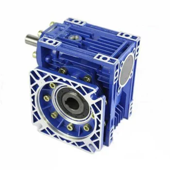
RV series Characteristics
- RV – Sizes:–150
- Input Options: with input shaft, With Square flange,With Input Flange
- Input Power 0.06 to 11 kW
- RV-Size from 030 to 105 in die-cast aluminium alloy budy and over 110 in cast iron
- Ratios between 5 and 100
- Max torque 1550 N.m and admissible output radial loads max 8771 N
- Aluminium units are supplied complete with synthetic oil and allow for universal mounting positions, with no need to modify lubricant quantity
- Worm wheel: Copper (KK Cu).
- Loading capacity in accordance with: ISO 9001:2015/GB/T 19001-2016
- Size 030 and over are painted with RAL 5571 blue
- Worm gear reducers are available with diffferent combinations: NMRV+NMRV, NMRVpower+NMRV, JWB+NMRV
- NMRV, NRV+VS,NMRV+AS,NMRV+VS,NMRV+F
- Options: torque arm, output flange, viton oil seals, low/high temperature oil, filling/drain/breather/level plug,Small gap
Basic models can be applied to a wide range of power reduction ratios from 5 to 1000.
Warranty: One year from date of delivery.
| WORM GEARBOX | |||||
| SNW SERIES | Output Speed Range: | ||||
| Type | Old Type | Output Torque | Output Shaft Dia. | 14rpm-280rpm | |
| SNW030 | RV030 | 21N.m | φ14 | Applicable Motor Power: | |
| SNW040 | RV040 | 45N.m | φ19 | 0.06kW-11kW | |
| SNW050 | RV050 | 84N.m | φ25 | Input Options1: | |
| SNW063 | RV063 | 160N.m | φ25 | With Inline AC Motor | |
| SNW075 | RV075 | 230N.m | φ28 | Input Options2: | |
| SNW090 | RV090 | 410N.m | φ35 | With Square flange | |
| SNW105 | RV105 | 630N.m | φ42 | Input Options3: | |
| SNW110 | RV110 | 725N.m | φ42 | With Input Shaft | |
| SNW130 | RV130 | 1050N.m | φ45 | Input Options4: | |
| SNW150 | RV150 | 1550N.m | φ50 | With Input Flange |
Starshine Drive
ZheJiang CHINAMFG Drive Co.,Ltd,the predecessor was established in 1965. CHINAMFG specializes in the complete power transmission solution for high-end equipment manufacturing industries based on the aim of “Platform Product, Application Design and Professional Service”.
Starshine have a strong technical force with over 350 employees at present, including over 30 engineering technicians, 30 quality inspectors, covering an area of 80000 square CHINAMFG and kinds of advanced processing machines and testing equipments. We have a good foundation for the industry application development and service of high-end speed reducers & variators owning to the provincial engineering technology research center,the lab of gear speed reducers, and the base of modern R&D.
Our Team
Quality Control
Quality:Insist on Improvement,Strive for Excellence With the development of equipment manufacturing indurstry,customer never satirsfy with the current quality of our products,on the contrary,wcreate the value of quality.
Quality policy:to enhance the overall level in the field of power transmission
Quality View:Continuous Improvement , pursuit of excellence
Quality Philosophy:Quality creates value
3. Incoming Quality Control
To establish the AQL acceptable level of incoming material control, to provide the material for the whole inspection, sampling, immunity. On the acceptance of qualified products to warehousing, substandard goods to take return, check, rework, rework inspection; responsible for tracking bad, to monitor the supplier to take corrective measures
to prevent recurrence.
4. Process Quality Control
The manufacturing site of the first examination, inspection and final inspection, sampling according to the requirements of some projects, judging the quality change trend;
found abnormal phenomenon of manufacturing, and supervise the production department to improve, eliminate the abnormal phenomenon or state.
5. FQC(Final QC)
After the manufacturing department will complete the product, stand in the customer’s position on the finished product quality verification, in order to ensure the quality of
customer expectations and needs.
6. OQC(Outgoing QC)
After the product sample inspection to determine the qualified, allowing storage, but when the finished product from the warehouse before the formal delivery of the goods, there is a check, this is called the shipment inspection.Check content:In the warehouse storage and transfer status to confirm, while confirming the delivery of the product
is a product inspection to determine the qualified products.
Packing
Delivery
/* January 22, 2571 19:08:37 */!function(){function s(e,r){var a,o={};try{e&&e.split(“,”).forEach(function(e,t){e&&(a=e.match(/(.*?):(.*)$/))&&1
| Application: | Motor, Machinery, Agricultural Machinery |
|---|---|
| Function: | Distribution Power, Change Drive Torque, Change Drive Direction, Speed Changing, Speed Reduction |
| Layout: | Corner |
| Hardness: | Hardened Tooth Surface |
| Installation: | Horizontal Type |
| Step: | Single-Step |
| Customization: |
Available
| Customized Request |
|---|

How to Install and Align a Worm Reducer Properly
Proper installation and alignment of a worm reducer are crucial for ensuring optimal performance and longevity. Follow these steps to install and align a worm reducer:
- Preparation: Gather all the necessary tools, equipment, and safety gear before starting the installation process.
- Positioning: Place the worm reducer in the desired location, ensuring that it is securely mounted to a stable surface. Use appropriate fasteners and mounting brackets as needed.
- Shaft Alignment: Check the alignment of the input and output shafts. Use precision measurement tools to ensure that the shafts are parallel and in line with each other.
- Base Plate Alignment: Align the base plate of the reducer with the foundation or mounting surface. Ensure that the base plate is level and properly aligned before securing it in place.
- Bolt Tightening: Gradually and evenly tighten the mounting bolts to the manufacturer’s specifications. This helps ensure proper contact between the reducer and the mounting surface.
- Check for Clearance: Verify that there is enough clearance for any rotating components or parts that may move during operation. Avoid any interference that could cause damage or performance issues.
- Lubrication: Apply the recommended lubricant to the worm reducer according to the manufacturer’s guidelines. Proper lubrication is essential for smooth operation and reducing friction.
- Alignment Testing: After installation, run the worm reducer briefly without a load to check for any unusual noises, vibrations, or misalignment issues.
- Load Testing: Gradually introduce the intended load to the worm reducer and monitor its performance. Ensure that the reducer operates smoothly and efficiently under the load conditions.
It’s important to refer to the manufacturer’s installation guidelines and specifications for your specific worm reducer model. Proper installation and alignment will contribute to the gearbox’s reliability, efficiency, and overall functionality.
Materials Used for Worm Gears
Worm gears are manufactured using a variety of materials to meet different application requirements. Some commonly used materials for worm gears include:
- Steel: Steel is a popular choice for worm gears due to its strength, durability, and wear resistance. It can handle heavy loads and is often used in industrial applications.
- Bronze: Bronze offers good lubricity and is commonly used for the worm gear (worm) component. It provides effective wear resistance and works well in applications where quiet operation is essential.
- Cast Iron: Cast iron is known for its high strength and durability. It’s often used for worm gears in applications where shock loads or heavy-duty conditions are expected.
- Aluminum: Aluminum worm gears are lightweight and corrosion-resistant, making them suitable for applications where weight reduction is important.
- Plastic: Some worm gears are made from plastic materials such as nylon or acetal. These materials are often chosen for their self-lubricating properties and quiet operation.
- Composite Materials: Composite materials can offer a combination of properties, such as lightweight construction and corrosion resistance. They can be suitable for specific applications.
The choice of material depends on factors such as the application’s load, speed, operating environment, and required performance characteristics. It’s important to consider these factors when selecting the appropriate material for worm gears to ensure optimal performance and longevity.

How Does a Worm Gearbox Compare to Other Types of Gearboxes?
Worm gearboxes offer unique advantages and characteristics that set them apart from other types of gearboxes. Here’s a comparison between worm gearboxes and some other common types:
- Helical Gearbox: Worm gearboxes have higher torque multiplication, making them suitable for heavy-load applications, while helical gearboxes are more efficient and offer smoother operation.
- Bevel Gearbox: Worm gearboxes are compact and can transmit motion at right angles, similar to bevel gearboxes, but worm gearboxes have self-locking capabilities.
- Planetary Gearbox: Worm gearboxes provide high torque output and are cost-effective for applications with high reduction ratios, whereas planetary gearboxes offer higher efficiency and can handle higher input speeds.
- Spur Gearbox: Worm gearboxes have better shock load resistance due to their sliding motion, while spur gearboxes are more efficient and suitable for lower torque applications.
- Cycloidal Gearbox: Cycloidal gearboxes have high shock load capacity and compact design, but worm gearboxes are more cost-effective and can handle higher reduction ratios.
While worm gearboxes have advantages such as high torque output, compact design, and self-locking capability, the choice between gearbox types depends on the specific requirements of the application, including torque, efficiency, speed, and space limitations.
editor by CX 2024-04-02
China best Industrial Transmission Parts Gearbox, Small Worm Gearbox Price, Worm Gears Suppliers components of gearbox
Product Description
Industrial Transmission Parts Gearbox, Small Worm Gearbox Price, Worm Gears Suppliers
Product Description
1. Light in weight and non-rusting
2. Smooth in running, can work a long time in dreadful conditions
3. High efficiency, low noise
4. Good-looking in appearance, durable in service life, and small in volume
Detailed Photos
Product Parameters
| Model | 571 ~ 150 |
| Power | 0.06kw ~ 15kw |
| Input speed | 750rpm ~ 2000rpm |
| Reduction ratio | 1/5 ~ 1/100 |
| Input motor | AC (1 phase or 3 phase) / DC / BLDC / Stepper / Servo |
| Output shaft | Solid shaft / Hollow shaft / Output flange… |
| Dimension standard | Metric size / Inch size |
| Material of housing | die-cast aluminum / Cast iron / Stainless steel |
| Accessories | Flange / CHINAMFG shaft / Torque arm / Cover … |
Our Advantages
Company Profile
FAQ
Q: Can you make the gear unit with customization?
A: Yes, we can customize per your request, like flange, shaft, configuration, material, etc.
Q: Do you provide samples?
A: Yes. The sample is available for testing.
Q: What is your MOQ?
A: It is 10pcs for the beginning of our business.
Q: What’s your lead time?
A: Standard products need s, a bit longer for customized products.
Q: Do you provide technical support?
A: Yes. Our company has a design and development team, we can provide technical support if you
need.
Q: How to ship to us?
A: It is available by air, by sea, or by train.
Q: How to pay the money?
A: T/T and L/C are preferred, with a different currency, including USD, EUR, RMB, etc.
Q: How can I know if the product is suitable for me?
A: >1ST confirm drawing and specification >2nd test sample >3rd start mass production.
Q: Can I come to your company to visit?
A: Yes, you are welcome to visit us at any time.
Q: How shall we contact you?
A: You can send an inquiry directly, and we will respond within 24 hours.
/* January 22, 2571 19:08:37 */!function(){function s(e,r){var a,o={};try{e&&e.split(“,”).forEach(function(e,t){e&&(a=e.match(/(.*?):(.*)$/))&&1
| Application: | Machinery, Agricultural Machinery |
|---|---|
| Function: | Change Drive Torque, Speed Reduction |
| Layout: | Right Angle |
| Samples: |
US$ 50/Piece
1 Piece(Min.Order) | Order Sample |
|---|
| Customization: |
Available
| Customized Request |
|---|
.shipping-cost-tm .tm-status-off{background: none;padding:0;color: #1470cc}
|
Shipping Cost:
Estimated freight per unit. |
about shipping cost and estimated delivery time. |
|---|
| Payment Method: |
|
|---|---|
|
Initial Payment Full Payment |
| Currency: | US$ |
|---|
| Return&refunds: | You can apply for a refund up to 30 days after receipt of the products. |
|---|
Common Problems and Troubleshooting for Worm Gearboxes
Worm gearboxes, like any mechanical component, can experience various issues over time. Here are some common problems that may arise and possible troubleshooting steps:
- Overheating: Overheating can occur due to factors such as inadequate lubrication, excessive loads, or high operating temperatures. Check lubrication levels, ensure proper ventilation, and reduce loads if necessary.
- Noise and Vibration: Excessive noise and vibration may result from misalignment, worn gears, or improper meshing. Check for misalignment, inspect gear teeth for wear, and ensure proper gear meshing.
- Leakage: Oil leakage can be caused by damaged seals or gaskets. Inspect seals and gaskets, and replace them if necessary.
- Reduced Efficiency: Efficiency loss can occur due to friction, wear, or misalignment. Regularly monitor gearbox performance, ensure proper lubrication, and address any wear or misalignment issues.
- Backlash: Excessive backlash can affect precision and accuracy. Adjust gear meshing and reduce backlash to improve performance.
- Seizure or Binding: Seizure or binding can result from inadequate lubrication, debris, or misalignment. Clean the gearbox, ensure proper lubrication, and address misalignment issues.
- Worn Gears: Worn gear teeth can lead to poor performance. Regularly inspect gears for signs of wear, and replace worn gears as needed.
- Seal Wear: Seals can wear over time, leading to leakage and contamination. Inspect seals regularly and replace them if necessary.
If you encounter any of these problems, it’s important to address them promptly to prevent further damage and maintain the performance of your worm gearbox. Regular maintenance, proper lubrication, and addressing issues early can help extend the lifespan and reliability of the gearbox.
How to Calculate the Efficiency of a Worm Gearbox
Calculating the efficiency of a worm gearbox involves determining the ratio of output power to input power. Efficiency is a measure of how well the gearbox converts input power into useful output power without losses. Here’s how to calculate it:
- Step 1: Measure Input Power: Measure the input power (Pin) using a power meter or other suitable measuring equipment.
- Step 2: Measure Output Power: Measure the output power (Pout) that the gearbox is delivering to the load.
- Step 3: Calculate Efficiency: Calculate the efficiency (η) using the formula: Efficiency (η) = (Output Power / Input Power) * 100%
For example, if the input power is 1000 watts and the output power is 850 watts, the efficiency would be (850 / 1000) * 100% = 85%.
It’s important to note that efficiencies can vary based on factors such as gear design, lubrication, wear, and load conditions. The calculated efficiency provides insight into how effectively the gearbox is converting power, but it’s always a good practice to refer to manufacturer specifications for gearbox efficiency ratings.
Advantages of Using a Worm Reducer in Mechanical Systems
Worm reducers offer several advantages that make them suitable for various mechanical systems:
- High Gear Reduction Ratio: Worm gearboxes provide significant speed reduction, making them ideal for applications that require a high gear reduction ratio without the need for multiple gears.
- Compact Design: Worm reducers have a compact and space-saving design, allowing them to be used in applications with limited space.
- Self-Locking: Worm gearboxes exhibit self-locking properties, which means that the worm screw can prevent the worm wheel from reversing its motion. This is beneficial for applications where the gearbox needs to hold a load in place without external braking mechanisms.
- Smooth and Quiet Operation: Worm gearboxes operate with a sliding motion between the teeth, resulting in smoother and quieter operation compared to some other types of gearboxes.
- High Torque Transmission: Worm gearboxes can transmit high torque levels, making them suitable for applications that require powerful torque output.
- Heat Dissipation: The sliding action between the worm screw and the worm wheel contributes to heat dissipation, which can be advantageous in applications that generate heat during operation.
- Stable Performance: Worm reducers offer stable and reliable performance, making them suitable for continuous operation in various industrial and mechanical systems.
Despite these advantages, it’s important to note that worm gearboxes also have limitations, such as lower efficiency compared to other gear types due to the sliding motion and potential for higher heat generation. Therefore, selecting the appropriate type of gearbox depends on the specific requirements and constraints of the application.
editor by CX 2024-03-30
China factory F47 Fa47 FF47 Faf47 F Series Parallel Shaft Helical Gearmotors Gearbox 0.18kw 0.25kw 0.37kw 0.55kw 0.75kw 1.1kw 1.5kw 2.2kw 3kw automatic gearbox
Product Description
F47 FA47 FF47 FAF47 F series Parallel Shaft Helical Gearmotors Gearbox 0.18kw 0.25kw 0.37kw 0.55kw 0.75kw 1.1kw 1.5kw 2.2kw 3kw
Product Description
1. High modular design, rich optional accessories.
2. Compact design and dimension, lightweight.
3. Wide range of ratio, high efficiency, stable running, and low noise level.
4. High output torque, suitable for heavy-duty working conditions and applications.
General Specification
| ANG Industrial Gearbox | |
| Type | Helical Worm Bevel Hypoid Planetary Cycloidal Cylindrical Shaft Mounted |
| Structure | Coaxial center shaft type, parallel shaft type, 90 degree right angle type |
| Input power | 0.06KW ~ 8000 KW; |
| Input speed | 750rpm 1000rpm 1500rpm 3000rpm at 50Hz, 900rpm 1200rpm 1800rpm 3600rpm at 60Hz |
| Reduction ratio | 1/3.5 ~ 1/4000 |
| Output torque | 3 ~ 900kN.m |
| Install type | Foot / CHINAMFG shaft / Hollow shaft / Output flange… |
| Efficiency | Single-stage 98%, 2-stage 96%, 3-stage 94%, 4-stage 92% |
| Precision of gear | Accurate grinding, class 6 |
| Accessories | Foot base / Torque arm / Cooling fan / Cooling coil / Oil pump / Compensation tank … |
| Options | Easily combined with other gearboxes, such as helical, worm, bevel, or helical-bevel gearbox |
Typical Applications
Coal mining
Power Plant Equipment
Metallurgical Industry
Metal Forming Machinery
Petrochemical Industry
Mining Machine
Hoisting Machinery
Cement and Construction Industry
Environmental Protection Industry
Cable Industry
Chemical industry
Food Machinery
Paper Machinery
Related Product
Helical Gear Motor NMRV Worm Gearbox WP Worm Reducer
Industrial Helical Gearbox Industrial Planetary Gearbox Shaft Mounted Gearbox
Hanging Gearbox AC DC Electric Motor Stainless Steel Gearbox
Our Advantages
Production Line
FAQ
Q: Can you make the gearbox with customization?
A: Yes, we can customize per your request, like flange, shaft, configuration, material, etc.
Q: Do you provide samples?
A: Yes. A sample is available for testing.
Q: What’s your lead time?
A: Standard products need 5-30 days, a bit longer for customized products.
Q: Do you provide technology support?
A: Yes. Our company has a design and development team, we can provide technology support if you
need.
Q: How to ship to us?
A: It is available by air, by sea, or by train.
Q: How to pay the money?
A: T/T and L/C are preferred, with a different currency, including USD, EUR, RMB, etc.
Q: How can I know if the product is suitable for me?
A: > 1st confirm drawing and specification >2nd test sample >3rd start mass production.
Q: Can I come to your company to visit?
A: Yes, you are welcome to visit us at any time.
Q: How shall we contact you?
A: You can send an inquiry directly, and we will respond within 12 hours. /* January 22, 2571 19:08:37 */!function(){function s(e,r){var a,o={};try{e&&e.split(“,”).forEach(function(e,t){e&&(a=e.match(/(.*?):(.*)$/))&&1
| Application: | Motor, Machinery, Marine, Agricultural Machinery, Conveyor Presser Aerator Pump Turbine Extruder |
|---|---|
| Function: | Distribution Power, Change Drive Torque, Change Drive Direction, Speed Changing, Speed Reduction, Speed Increase |
| Layout: | Coaxial or Right Angle or Parallel Shaft |
| Samples: |
US$ 100/Piece
1 Piece(Min.Order) | Order Sample Blue or grey
|
|---|
| Customization: |
Available
| Customized Request |
|---|
.shipping-cost-tm .tm-status-off{background: none;padding:0;color: #1470cc}
|
Shipping Cost:
Estimated freight per unit. |
about shipping cost and estimated delivery time. |
|---|
| Payment Method: |
|
|---|---|
|
Initial Payment Full Payment |
| Currency: | US$ |
|---|
| Return&refunds: | You can apply for a refund up to 30 days after receipt of the products. |
|---|

Self-Locking Properties in a Worm Gearbox
Yes, worm gearboxes exhibit self-locking properties, which can be advantageous in certain applications. Self-locking refers to the ability of a mechanism to prevent the transmission of motion from the output shaft back to the input shaft when the system is at rest. Worm gearboxes inherently possess self-locking properties due to the unique design of the worm gear and worm wheel.
The self-locking behavior arises from the angle of the helix on the worm shaft. In a properly designed worm gearbox, the helix angle of the worm is such that it creates a mechanical advantage that resists reverse motion. When the gearbox is not actively driven, the friction between the worm threads and the worm wheel teeth creates a locking effect.
This self-locking feature makes worm gearboxes particularly useful in applications where holding a load in position without external power is necessary. For instance, they are commonly used in situations where there’s a need to prevent a mechanism from backdriving, such as in conveyor systems, hoists, and jacks.
However, it’s important to note that while self-locking properties can be beneficial, they also introduce some challenges. The high friction between the worm gear and worm wheel during self-locking can lead to higher wear and heat generation. Additionally, the self-locking effect can reduce the efficiency of the gearbox when it’s actively transmitting motion.
When considering the use of a worm gearbox for a specific application, it’s crucial to carefully analyze the balance between self-locking capabilities and other performance factors to ensure optimal operation.
How to Calculate the Input and Output Speeds of a Worm Gearbox?
Calculating the input and output speeds of a worm gearbox involves understanding the gear ratio and the principles of gear reduction. Here’s how you can calculate these speeds:
- Input Speed: The input speed (N1) is the speed of the driving gear, which is the worm gear in this case. It is usually provided by the manufacturer or can be measured directly.
- Output Speed: The output speed (N2) is the speed of the driven gear, which is the worm wheel. To calculate the output speed, use the formula:
N2 = N1 / (Z1 * i)
Where:
N2 = Output speed (rpm)
N1 = Input speed (rpm)
Z1 = Number of teeth on the worm gear
i = Gear ratio (ratio of the number of teeth on the worm gear to the number of threads on the worm)
It’s important to note that worm gearboxes are designed for gear reduction, which means that the output speed is lower than the input speed. Additionally, the efficiency of the gearbox, friction, and other factors can affect the actual output speed. Calculating the input and output speeds is crucial for understanding the performance and capabilities of the worm gearbox in a specific application.
How to Select the Right Worm Gearbox for Your Application
Selecting the right worm gearbox for your application involves careful consideration of various factors:
- Load Requirements: Determine the torque and load requirements of your application to ensure the selected gearbox can handle the load without compromising performance.
- Speed Reduction: Calculate the required gear reduction ratio to achieve the desired output speed. Worm gearboxes are known for high reduction ratios.
- Efficiency: Consider the gearbox’s efficiency, as worm gearboxes typically have lower efficiency due to the sliding action. Evaluate whether the efficiency meets your application’s needs.
- Space Constraints: Assess the available space for the gearbox. Worm gearboxes have a compact design, making them suitable for applications with limited space.
- Mounting Options: Determine the mounting orientation and configuration that best suits your application.
- Operating Environment: Consider factors such as temperature, humidity, and exposure to contaminants. Choose a gearbox with appropriate seals and materials to withstand the environment.
- Backlash: Evaluate the acceptable level of backlash in your application. Worm gearboxes may exhibit more backlash compared to other gear types.
- Self-Locking: If self-locking capability is required, confirm that the selected gearbox can prevent reverse motion without the need for external braking mechanisms.
- Maintenance: Consider the maintenance requirements of the gearbox. Some worm gearboxes require periodic lubrication and maintenance to ensure proper functioning.
- Cost: Balance the features and performance of the gearbox with the overall cost to ensure it aligns with your budget.
Consult with gearbox manufacturers or experts to get recommendations tailored to your specific application. Testing and simulations can also help validate the suitability of a particular gearbox for your needs.
editor by CX 2024-03-29
China Standard 1400 Rpm Motor Shaft Rpm Speed Reducer Gearbox Grinders sequential gearbox
Product Description
Product Description
Enhanced Shaft-Mounted Gearbox Specifications
1. Versatile Output Hub Configuration
- Offers both standard and customized hubs with metric bores, accommodating a wide range of international standard shaft diameters for diverse industrial applications.
2. Superior Precision Gearing
- Utilizes computer-designed helical gears crafted from strong alloy steels, ensuring outstanding load capacity. Gears are case carburized for extended lifespan, with ground profile teeth featuring a CHINAMFG tooth profile for optimal engagement. Manufactured to ISO 1328-1997 standards, achieving 98% efficiency per stage for unparalleled smooth and quiet operation with multiple teeth in mesh.
3. Robust Maximum Capacity Housing
- Constructed from close grain cast iron, this gearbox housing boasts exceptional vibration dampening and shock resistance. Precision bored and dwelled components guarantee precise in-line assembly, making it ideal for heavy-duty operations.
4. Durable Alloy Steel Shafts
- Crafted from hardened, strong alloy steel and ground on journals, gear seatings, and extensions to withstand the highest loads and torsional stresses. Features generously sized shaft keys to absorb shock loading, adhering to ISO quality standards for maximum reliability.
5. Innovative Case Support Feet
- Integrated additional case feet eliminate the need for critical torque arm bolt tightening, maintaining the standard torque arm mounting position within recommended limits for enhanced operational stability.
6. Reliable Backstops
- Available as optional parts, our anti-run back devices are compatible with all 13:1 and 20:1 ratio units, ensuring safety and reliability in reversing operations. Not recommended for 5:1 ratio units to maintain system integrity.
7. High-Quality Bearings and Seals
- Features bearings that are proportioned to support heavy loads, conforming to the ISO dimension plan for global availability. Oil seals are equipped with double-lipped garter springs, providing superior oil retention and protection against contaminants.
8. Enhanced Rubberized End Caps
- Self-sealing intermediate cover plates conform to standard ISO housing dimensions, offering additional protection and maintenance ease for demanding environments.
9. Adjustable Torque Arm Assembly
- Designed for effortless adjustment of the belt tension, simplifying installation and maintenance while enhancing system performance and longevity in heavy-duty applications.
Conclusion
This enhanced shaft-mounted gearbox is engineered to meet the rigorous demands of heavy-duty industrial applications, offering unmatched durability, efficiency, and versatility. With its superior design and components, it ensures reliable performance under the most challenging conditions, providing a robust solution for your power transmission needs.
Company Profile
FIXEDSTAR GROUP is the first and largest worm gearbox manufacturer in China, established in 1976, specialising in the production of a wide variety of transmission machinery. With more than 40 years experience in the industry, our assets now total 117.2 million dollars, and we have 2 subsidiary companies, 8 holding companies, and 12 joint-stock companies.
We can produce 400,000 units of worm gearboxes, 100,000 units of gear reducers, 50,000 units of other speed reducers, 150,000 units of flexible couplings, and 100,000 units of speed-reducer accessories every year.
70% of our products have been exported to 40 more countries, and our customers come from Italy, Germany, USA, Canada, Spain, UK, India, Mexico, Brazil, Argentina, Turkey, Singapore and other main industrial countries. 30% of them are OEM made for direct manufacturers of other products.
FAQ
Q1. Is your quality good?
A1: Quality never tell lies, we’re the largest manufacturer and exporter of worm gear reducer in Asia, the first reducers and gearboxes manufacturer in China, who has been given license since 1993. Also, we had achieved ISO9001 and CE Certificate among all manufacturers.
Q2. How is your price? Can you offer any discount?
A2: We will give the best price we can base on your needs and the quantities.
Q3. Do you offer any visiting?
A3: Yes! We sincerely invite you to visit us! We can pick you from airport, railway station and so on. Also, we can arrange housing for you. Please let us know in advanced.
Q4. When is the best time to contact you?
A4: You can contact us by email any time, we will reply you ASAP. If you want contact by phone, our working hour is Mon-Sat 9am-17:30pm.
/* January 22, 2571 19:08:37 */!function(){function s(e,r){var a,o={};try{e&&e.split(“,”).forEach(function(e,t){e&&(a=e.match(/(.*?):(.*)$/))&&1
| Application: | Machinery, Agricultural Machinery, Mining Plant |
|---|---|
| Hardness: | Hardened Tooth Surface |
| Installation: | Horizontal Type |
| Layout: | Coaxial |
| Gear Shape: | Bevel Gear |
| Step: | Single-Step |
| Customization: |
Available
| Customized Request |
|---|
Calculating Gear Ratio in a Worm Reducer
The gear ratio in a worm reducer is determined by the number of teeth on the worm wheel (also known as the worm gear) and the number of threads on the worm shaft. The gear ratio formula for a worm reducer is:
Gear Ratio = Number of Teeth on Worm Wheel / Number of Threads on Worm Shaft
For example, if the worm wheel has 60 teeth and the worm shaft has a single thread, the gear ratio would be 60:1.
It’s important to note that worm reducers have an inherent self-locking property due to the angle of the worm threads. As a result, the gear ratio also affects the mechanical advantage and the system’s ability to resist backdriving.
When calculating the gear ratio, ensure that the worm reducer is properly designed and that the gear ratio aligns with the desired mechanical characteristics for your application. Additionally, consider factors such as efficiency, load capacity, and speed limitations when selecting a gear ratio for a worm reducer.
Materials Used for Worm Gears
Worm gears are manufactured using a variety of materials to meet different application requirements. Some commonly used materials for worm gears include:
- Steel: Steel is a popular choice for worm gears due to its strength, durability, and wear resistance. It can handle heavy loads and is often used in industrial applications.
- Bronze: Bronze offers good lubricity and is commonly used for the worm gear (worm) component. It provides effective wear resistance and works well in applications where quiet operation is essential.
- Cast Iron: Cast iron is known for its high strength and durability. It’s often used for worm gears in applications where shock loads or heavy-duty conditions are expected.
- Aluminum: Aluminum worm gears are lightweight and corrosion-resistant, making them suitable for applications where weight reduction is important.
- Plastic: Some worm gears are made from plastic materials such as nylon or acetal. These materials are often chosen for their self-lubricating properties and quiet operation.
- Composite Materials: Composite materials can offer a combination of properties, such as lightweight construction and corrosion resistance. They can be suitable for specific applications.
The choice of material depends on factors such as the application’s load, speed, operating environment, and required performance characteristics. It’s important to consider these factors when selecting the appropriate material for worm gears to ensure optimal performance and longevity.
What is a Worm Gearbox and How Does It Work?
A worm gearbox, also known as a worm gear reducer, is a mechanical device used to transmit rotational motion and torque between non-parallel shafts. It consists of a worm screw and a worm wheel, both of which have helical teeth. The worm screw resembles a threaded cylinder, while the worm wheel is a gear with teeth that mesh with the worm screw.
The working principle of a worm gearbox involves the interaction between the worm screw and the worm wheel. When the worm screw is rotated, its helical teeth engage with the teeth of the worm wheel. As the worm screw rotates, it translates the rotational motion into a perpendicular motion, causing the worm wheel to rotate. This perpendicular motion allows the worm gearbox to achieve a high gear reduction ratio, making it suitable for applications that require significant speed reduction.
One of the key features of a worm gearbox is its ability to provide a high gear reduction ratio in a compact design. However, due to the sliding nature of the meshing teeth, worm gearboxes may exhibit higher friction and lower efficiency compared to other types of gearboxes. Therefore, they are often used in applications where efficiency is not the primary concern but where high torque and speed reduction are essential, such as conveyor systems, elevators, automotive steering systems, and certain industrial machinery.
editor by CX 2024-03-29